FT245R 데이터 시트보기 (PDF) - Future Technology
부품명
상세내역
제조사
FT245R Datasheet PDF : 37 Pages
| |||
Document No.: FT_000052
FT245R USB FIFO IC Datasheet Version 2.12
Clearance No.: FTDI# 39
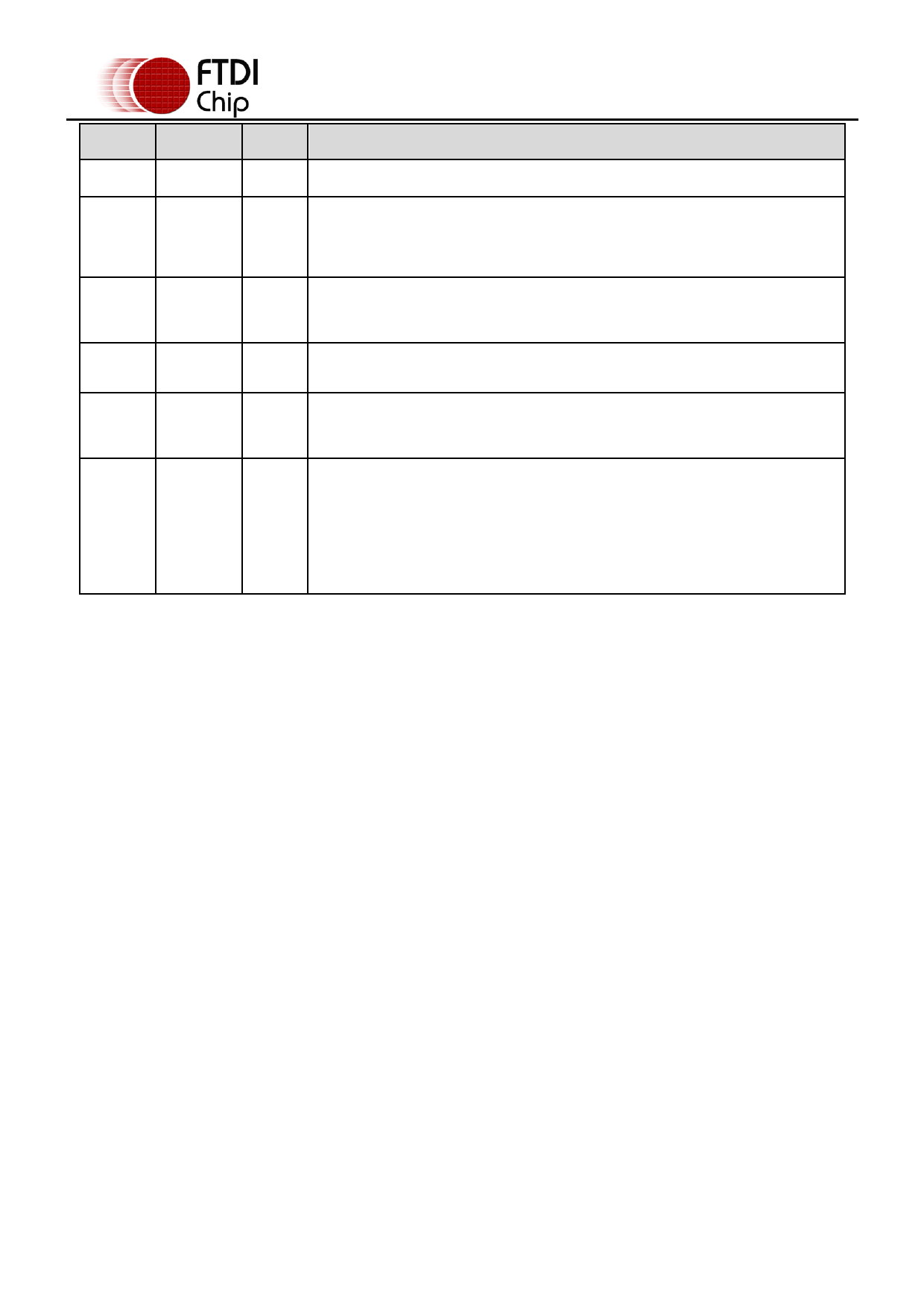
Pin No. Name
Type
Description
11
D3
I/O
FIFO Data Bus Bit 3
Goes low after the device is configured by USB, then high during USB suspend.
12
PWREN#
Output
Can be used to control power to external logic P-Channel logic level MOSFET
switch. Enable the interface pull-down option when using the PWREN# pin in this
way. Should be pulled to VCCIO with 10kΩ resistor.
Enables the current FIFO data byte on D0...D7 when low. Fetched the next FIFO
13
RD#
Input data byte (if available) from the receive FIFO buffer when RD# goes from high to
low. See Section 3.5 for timing diagram.
14
WR
Input
Writes the data byte on the D0...D7 pins into the transmit FIFO buffer when WR
goes from high to low. See Section 3.6 for timing diagram.
When high, do not write data into the FIFO. When low, data can be written into
22
TXE#
Output the FIFO by strobing WR high, then low. During reset this signal pin is tri-state.
See Section 3.6 for timing diagram.
When high, do not read data from the FIFO. When low, there is data available in
the FIFO which can be read by strobing RD# low, then high again. During reset
this signal pin is tri-state. See Section 3.5 for timing diagram.
23
RXF
Output If the Remote Wakeup option is enabled in the internal EEPROM, during USB
suspend mode (PWREN# = 1) RXF# becomes an input. This can be used to wake
up the USB host from suspend mode by strobing this pin low for a minimum of
20ms which will cause the device to request a resume on the USB bus.
Table 3.4 FIFO Interface Group (see note 3)
Notes:
1. The minimum operating voltage VCC must be +4.0V (could use VBUS=+5V) when using the
internal clock generator. Operation at +3.3V is possible using an external crystal oscillator.
2. For details on how to use an external crystal, ceramic resonator, or oscillator with the FT245R,
please refer Section 8.2
3. When used in Input Mode, the input pins are pulled to VCCIO via internal 200kΩ resistors. These
pins can be programmed to gently pull low during USB suspend (PWREN# = “1”) by setting an
option in the internal EEPROM.
Copyright © 2010 Future Technology Devices International Limited
9
Share Link: 