MMBTA42-7-F_15 데이터 시트보기 (PDF) - Diodes Incorporated.
부품명
상세내역
제조사
MMBTA42-7-F_15 Datasheet PDF : 5 Pages
| |||
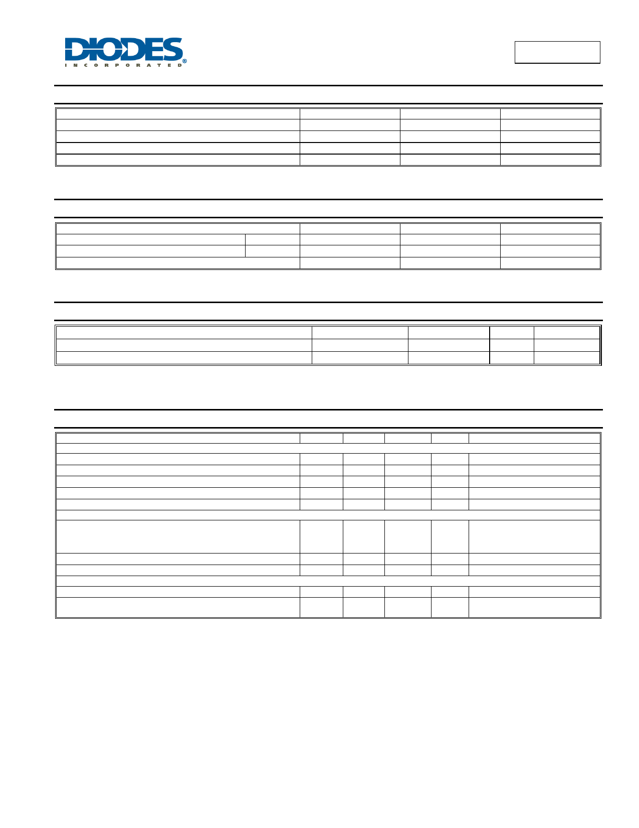
Absolute Maximum Ratings (@TA = +25°C, unless otherwise specified.)
Characteristic
Collector-Base Voltage
Collector-Emitter Voltage
Emitter-Base Voltage
Collector Current - Continuous
Symbol
VCBO
VCEO
VEBO
IC
Value
300
300
6.0
500
MMBTA42
Unit
V
V
V
mA
Thermal Characteristics (@TA = +25°C, unless otherwise specified.)
Characteristic
Power Dissipation
Thermal Resistance, Junction to Ambient
Operating and Storage Temperature Range
(Note 6)
(Note 6)
Symbol
PD
RJA
TJ, TSTG
Value
300
417
-55 to +150
Unit
mW
°C/W
°C
ESD Ratings (Note 7)
Characteristic
Electrostatic Discharge - Human Body Model
Electrostatic Discharge - Machine Model
Symbol
ESD HBM
ESD MM
Value
4,000
400
Unit JEDEC Class
V
3A
V
C
Notes:
6. For a device mounted on minimum recommended pad layout 1oz copper that is on a single-sided FR4 PCB; device is measured under still air
conditions whilst operating in a steady-state.
7. Refer to JEDEC specification JESD22-A114 and JESD22-A115.
Electrical Characteristics (@TA = +25°C, unless otherwise specified.)
Characteristic
OFF CHARACTERISTICS (Note 8)
Collector-Base Breakdown Voltage
Collector-Emitter Breakdown Voltage
Emitter-Base Breakdown Voltage
Collector Cut-Off Current
Emitter Cut-Off Current
ON CHARACTERISTICS (Note 8)
DC Current Gain
Collector-Emitter Saturation Voltage
Base-Emitter Saturation Voltage
SMALL SIGNAL CHARACTERISTICS
Output Capacitance
Current Gain-Bandwidth Product
Symbol Min
BVCBO
300
BVCEO
300
BVEBO
6.0
ICBO
IEBO
25
hFE
40
40
VCE(SAT)
VBE(SAT)
Ccb
fT
50
Note:
8. Measured under pulsed conditions. Pulse width ≤ 300µs. Duty cycle ≤ 2%.
Max
100
100
0.5
0.9
3.0
Unit
Test Condition
V IC = 100µA, IE = 0
V IC = 1.0mA, IB = 0
V IE = 100µA, IC = 0
nA VCB = 200V, IE = 0
nA VEB = 6.0V, IC = 0
IC = 1.0mA, VCE = 10V
IC = 10mA, VCE = 10V
IC = 30mA, VCE = 10V
V IC = 20mA, IB = 2.0mA
V IC = 20mA, IB = 2.0mA
pF
MHz
VCB = 20V, f = 1.0MHz, IE = 0
VCE = 20V, IC = 10mA,
f = 100MHz
MMBTA42
Document number: DS30062 Rev. 12 - 2
2 of 5
www.diodes.com
October 2015
© Diodes Incorporated
Share Link: 