STK4065 데이터 시트보기 (PDF) - SANYO -> Panasonic
부품명
상세내역
제조사
STK4065 Datasheet PDF : 9 Pages
| |||
STK4065
Operating Characteristics at Ta = 25°C, RL = 2Ω, Rg = 600Ω, VG = 46dB, VCC = 13.2V
Parameter
Symbol
Conditions
min
typ
max
Unit
Quiescent current
Output power
ICCO
PO(1)
PO(2)
PO(3)
Rg = 10kΩ
THD = 10%, f = 1kHz
THD = 1%, f = 1kHz
THD = 10%, RL = 4Ω,
f = 1kHz
–
70
140
mA
25
35
–
W
–
25
–
W
20
23
–
W
Total harmonic distortion
THD(1)
PO = 10W, f = 1kHz
–
THD(2)
PO = 1W, f = 20Hz to 20kHz
–
0.06
0.1
%
–
0.3
%
Voltage gain
Frequency response
Input impedance
VG
PO = 1W, f = 1kHz
fL, fH
PO
=
1W,
+0
−3
dB
ri
PO = 1W, f = 1kHz
43.8
46.0
48.2
dB
–
10 to 30k
–
Hz
20
30
–
kΩ
Output noise voltage
VNO
Rg = 10kΩ, without BPF
–
0.6
1.2
mVrms
Output offset voltage
∆VN
Rg = 10kΩ
−200
0
+200
mV
Muting suppression level
ATT
VM = +5V
–
∞
–
dB
Ripple rejection
SVRR
fR = 100Hz, Rg = 0Ω,
VR = 0dBm
–
–47
–
dB
* It is guaranteed that load short causes no damage for 2 seconds. In actual applications, the thermal shutdown protector provides sufficient guarantee against load
short. However, refer to “Notes for Applying the STK4065”, because the saturation current varies with the thermal resistance of the heat sink.
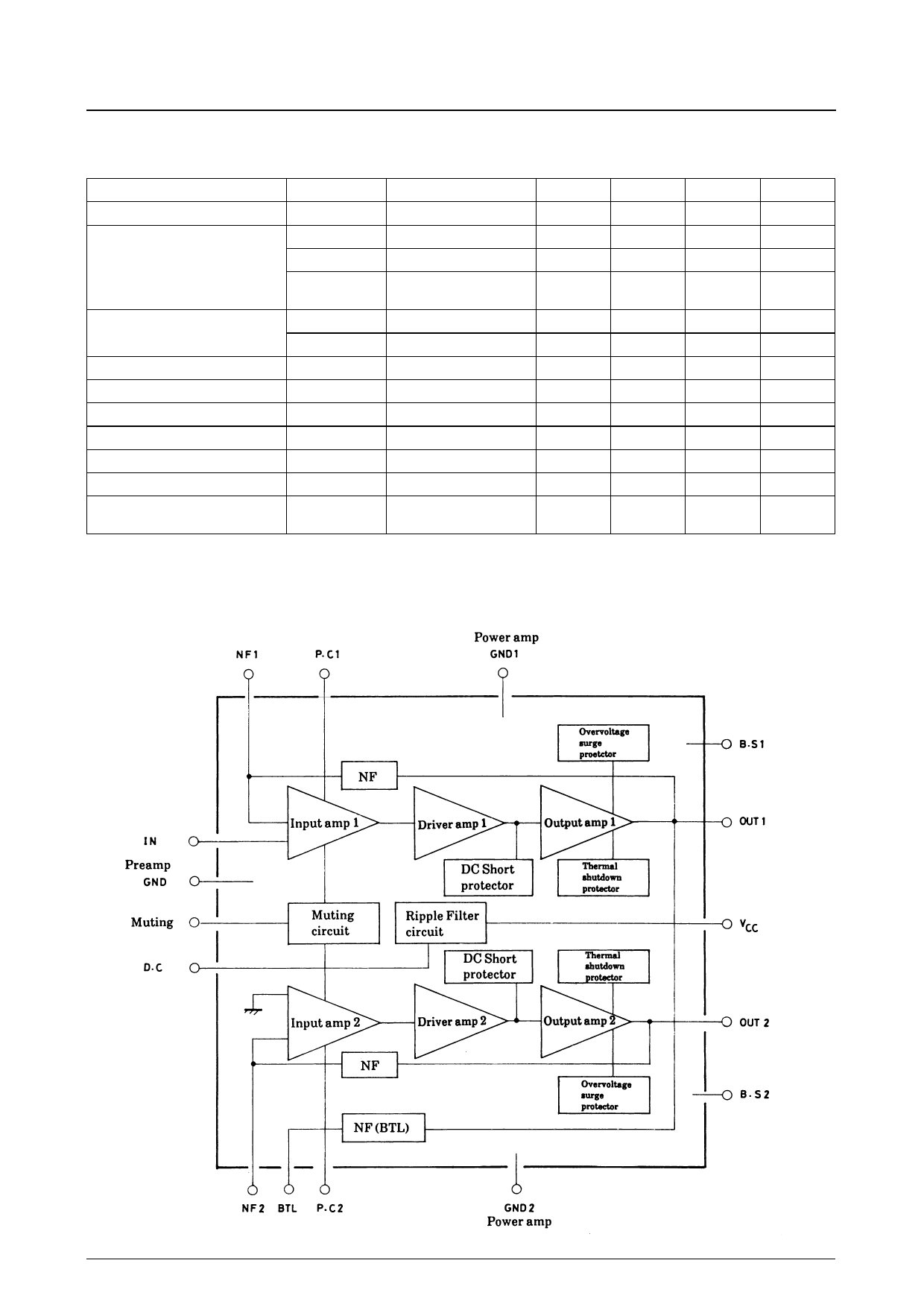
Equivalent Circuit Block Diagram
No. 2148—2/9
Share Link: 