LM234Z-6 데이터 시트보기 (PDF) - Linear Technology
부품명
상세내역
제조사
LM234Z-6 Datasheet PDF : 12 Pages
| |||
LM134 Series
APPLICATIO S I FOR ATIO
Lead Resistance
The sense voltage which determines the operating current
of the LM134 is less than 100mV. At this level, thermo-
couple or lead resistance effects should be minimized by
locating the current setting resistor physically close to the
device. Sockets should be avoided if possible. It takes only
0.7Ω contact resistance to reduce output current by 1% at
the 1mA level.
Start-Up Time
The LM134 is designed to operate at currents as low as
1µA. This requires that internal biasing current be well
below that level because the device achieves its wide
operating current range by using part of the operating
current as bias current for the internal circuitry. To ensure
start-up, however, a fixed trickle current must be provided
internally. This is typically in the range of 20nA to 200nA
and is provided by the special ultralow IDDS FETs shown in
the Schematic Diagrams as Q7 and Q8. The start-up time
of the LM134 is determined by the IDSS of these FETs and
the capacitor C1. This capacitor must charge to approxi-
mately 500mV before Q3 turns on to start normal circuit
operation. This takes as long as (500mV)(50pF)/(20nA) =
1.25ms for very low IDSS values.
Using the LM134 as a Temperature Sensor
Because it has a highly linear output characteristic, the
LM134 makes a good temperature sensor. It is particularly
useful in remote sensing applications because it is a
current output device and is therefore not affected by long
wire runs. It is easy to calibrate, has good long term
stability and can be interfaced directly with most data
acquisition systems, eliminating the expensive preampli-
fiers required for thermocouples and platinum sensors.
A typical temperature sensor application is shown in
Figure␣ 2. The LM134 operating current at 25°C is set at
298µA by the 226Ω resistor, giving an output of 1µA/°K.
The current flows through the twisted pair sensor leads to
the 10k termination resistor, which converts the current
output to a voltage of 10mV/°K referred to ground. The
voltage across the 10k resistor will be 2.98V at 25°C, with
a slope of 10mV/°C. The simplest way to convert this
signal to a Centigrade scale is to subtract a constant 2.73V
in software. Alternately, a hardware conversion can be
used, as shown in Figure 3, using an LT1009 as a level
shifter to offset the output to a Centigrade scale.
The resistor (RSET) used to set the operating current of the
LM134 in temperature sensing applications should have
low temperature coefficient and good long term stability.
A 30ppm/°C drift in the resistor will change the slope of the
temperature sensor by 1%, assuming that the resistor is
at the same temperature as the sensor, which is usually the
case since the resistor should be located physically close
to the LM134 to prevent errors due to wire resistance. A
long term shift of 0.3% in the resistor will create a 1°C
temperature error. The long term drift of the LM134 is
typically much better than this, so stable resistors must be
used for best long term performance.
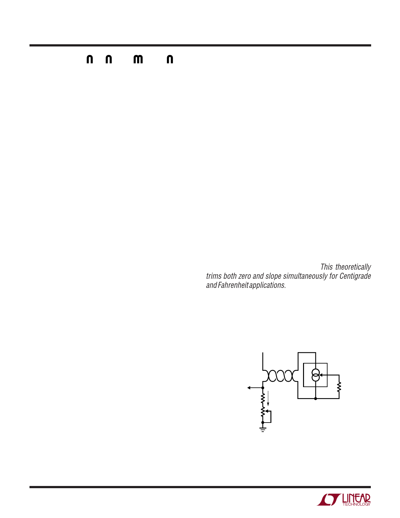
Calibration of the LM134 as a temperature sensor is
extremely easy. Referring to Figure 2, calibration is achieved
by trimming the termination resistor. This theoretically
trims both zero and slope simultaneously for Centigrade
and Fahrenheit applications. The initial errors in the LM134
are directly proportional to absolute temperature, just like
the actual output. This allows the sensor to be trimmed at
any temperature and have the slope error be corrected at
the same time. Residual slope error is typically less than
1% after this single trim is completed.
VS ≥ 5V
TO DATA
ACQUISITION
SYSTEM
10mV/°K 9.53k
1k
CALIBRATE
I = 1µA/°K
V+
LM234-3
R
RSET
V–
226Ω
134 F02
Figure 2 Kelvin Temperature Sensor
6
Share Link: 