TL431AC 데이터 시트보기 (PDF) - STMicroelectronics
부품명
상세내역
제조사
TL431AC Datasheet PDF : 9 Pages
| |||
TL431
ABSOLUTE MAXIMUM RATINGS
Symbol
VKA
IK
Iref
To per
Tst g
Parameter
Cathode to Anode Voltage
Continuous Cathode Current Range
Reference Input Current Range
Operating Free-air Temperature Range TL431C/AC
TL431I/AI
Storage Temperature Range
Value
Unit
37
V
-100 to +150
mA
-0.05 to +10
mA
0 to +70
oC
-40 to +105
-65 to +150
oC
OPERATING CONDITIONS
Symbol
VKA
IK
Parameter
Cathode to Anode Voltage
Cathode Current
Value
Vref to 36
1 to 100
Unit
V
mA
ELECTRICAL CHARACTERISTICS
Tamb = 25oC (unless otherwise specified)
Symbol
Vref
∆Vref
∆Vref
∆VKA
Iref
∆Iref
Imin
Ioff
|ZKA|
Parameter
Reference Input Voltage - (figure 1)
VKA = Vref, IK = 10mA
Tamb = 25oC
Tmin. ≤ Tamb ≤ Tmax.
Reference Input Voltage Deviation Over
Temperature Range - (figure 1, note1)
VKA = Vref, IK = 10mA, Tmin. ≤ Tamb ≤ Tmax.
Ratio of Change in Reference Input Voltage to
Change in Cathode to Anode Voltage - (figure 2)
IK = 10mA
∆VKA = 10V to Vref
∆VKA = 36V to 10V
Reference Input Current - (figure 2)
IK = 10mA, R1 = 10TkaΩm,bR=22=5∞oC
Tmin. ≤ Tamb ≤ Tmax.
Reference Input Current Deviation Over
Temperature Range - (figure 2)
IK = 10mA, R1 = 10kΩ, R2 = ∞
Tmin. ≤ Tamb ≤ Tmax.
Minimum Cathode Current for Regulation - (figure 1)
VKA = Vref
Off-State Cathode Current - (figure 3)
Dynamic Impedance - (figure 1, note 2)
VKA = Vref, ∆IK = 1 to 100mA, f ≤ 1kHz
TL431C
Min. Typ. Max.
2.44 2.495 2.55
2.423
2.567
3
17
-1.4 -2.7
-1
-2
1.8 4
5.2
0.4 1.2
0.5 1
2.6 1000
0.22 0.5
TL 431AC
Min. Typ. Max.
2.47 2.495 2.52
2.453
2.537
3
15
-1.4 -2.7
-1
-2
1.8 4
5.2
0.4 1.2
0.5 0.6
2.6 1000
0.22 0.5
Unit
V
mV
mV/V
µA
µA
mA
nA
Ω
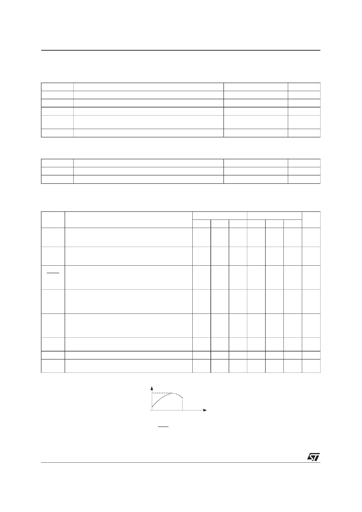
Notes : 1.
∆Vref is defined as the difference between the maximum and minimum values obtained over the full temperature
range.
∆Vref = Vref max. - Vref min
V ref ma x.
Vre fmin.
T1
T2
Tempe ra tur e
2.
The
dynamic
Impedance
is
defined
as
|ZKA|
=
∆VKA
∆IK
2/9
Share Link: 