LXT331 데이터 시트보기 (PDF) - Pulse Electronics
부품명
상세내역
제조사
LXT331 Datasheet PDF : 5 Pages
| |||
T1/E1/CEPT/ISDN-PRI TRANSFORMERS
Quad Port T1/E1 with 8 Transformers, 1500 Vrms
Application
1. ET Product - All coils have an ET product of 10 V-μsec
minimum.
2. Flammability - Materials used in the products are
recognized as UL94-VO approved. Products meet the
IEC 695-2-2 requirements (Needle Flame Test).
3. Balance Characteristics - The transformers meet the
requirements for longitudinal balance of FCC part 68.
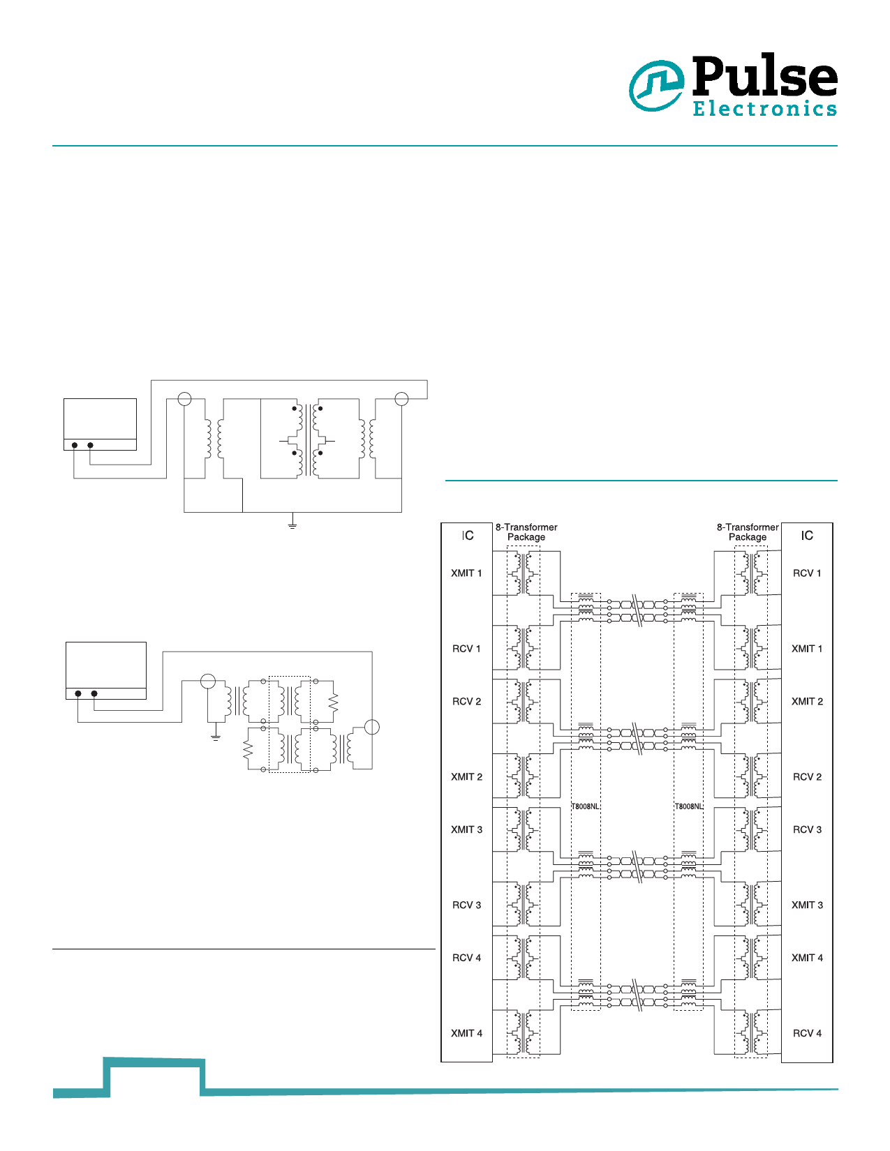
4. Common Mode Rejection Ratio - the CMRR for all
transformers is better than 50dB at 1MHz. A typical test
circuit is shown below.
HP-8751A
P1 P2
50:100
BALUN
XFMR
100:50
BALUN
Metallic Voltage: 800 V peak, 10/560μsec
Longitudinal Voltage:
2,400 V peak, 10/700μsec
8. Isolation Voltage - 100% of transformers are tested during the
specified isolation voltage level.
9. General Information - The transformers are specifically designed
for use in 1.544 Mbps (T1), 2.048 Mbps (CEPT) and ISDN Primary
rate (PRI) interface applications. They are matched to the
majority of the line interface transceiver ICs currently available.
Use of the proper transformer allows the interface circuit to
comply with ITU-T G.703 and other standards regarding pulse
waveform, return loss, and balance.
10. Common Mode Chokes - Additional high-frequency 4-line
common mode chokes may be used to provide an effective
means of complying with national and international regulations
on EMI. The common mode chokes are designed to be used in
conjunction with Pulse’s T1/CEPT transformers as shown in the
typical application below. Crosstalk is typically -65 dB or better.
Typical Application
5. Crosstalk Attentuation - In the packages which contain
transmit and receive transformers side by side, sufficient
crosstalk attentuation is achieved by the inherent
characteristics of the toroid cores as well as by their
proper positioning. The crosstalk attentuation is typically
65 dB or better. This result was established with the test
circuit shown below.
HP-8751A
P1 P2
50:100
BALUN
100
100
XFMR 100:50
BALUN
6. Return Loss - ITU-T G.703 and European national
regulatory documents specify minimum return loss levels.
The transformers will allow these limits to be complied
with the situations where they are applicable.
Frequency
50-100 kHz 10 kHz-2MHz 2-3 MHz
Return Loss
Transmit
9 dB
15 dB
11 dB
Receive
12 dB
18 dB
14 B
7. Surge Voltage Capability - All transformers and chokes meet
surge voltage tests according to the most stringent regulatory
documents, when used with the proper voltage and current
suppression devices:
3
pulseelectronics.com
T622.K (04/12)
Share Link: 