AZ10EP16VST 데이터 시트보기 (PDF) - AZ Microtek
부품명
상세내역
제조사
AZ10EP16VST Datasheet PDF : 10 Pages
| |||
AZ10EP16VS
AZ100EP16VS
AC Characteristics (VEE = -3.0 to -3.6V, VCC = GND, VCTRL=VREF or VEE = GND, VCC = +3.0V to 3.6V, VCTRL = VREF)
Symbol
Characteristic
-40°C
0°C
25°C
85°C
Unit
Min Typ Max Min Typ Max Min Typ Max Min Typ Max
fmax
Maximum Toggle
Frequency5
>4
>4
>4
>4
GHz
tPLH / tPHL
Input to Output
Delay
(Diff) 100
(SE)
150
155
240
100
150
155
240
100
150
155
240
120
170
175
280
ps
tSKEW
Duty Cycle Skew1 (Diff)
4
20
4
15
4
15
4
15
ps
Vpp
Minimum Input Swing2
150
150
150
150
mV
VCMR
Common Mode Range3
VEE +
2.0
VCC
VEE +
2.0
VCC
VEE +
2.0
VCC
VEE +
2.0
VCC
V
Av
Small Signal Gain4
28
dB
tr / tf
Output Rise/Fall Times Q
(20% - 80%)
120 170
120 180
120 180
120 200
ps
1. Duty cycle skew is the difference between a tPLH and tPHL propagation delay through a device.
2. VPP is the minimum peak-to-peak differential input swing for which AC parameters are guaranteed.
3. The VCMR range is referenced to the most positive side of the differential input signal. Normal operation is obtained if the HIGH level falls within
the specified range and the peak-to-peak voltage lies between VPP(min) and 1V.
4. Differential input, differential output. 240Ω to VEE on Q/Q¯ outputs, VCTRL = NC and BOOST = VEE (for MLP 16 package).
5. See graph below.
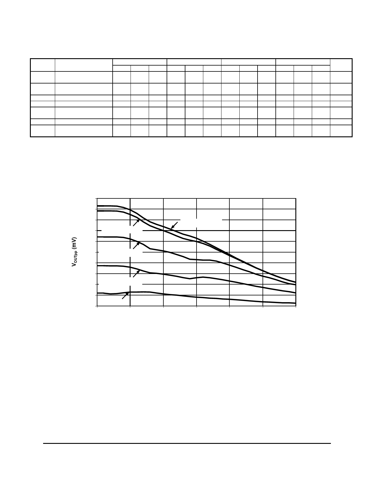
Typical Large Signal Performance, AZ100EP16VS*
1000
900
800
700 VCTRL=VCC-1.5V
600
500
400
VCTRL=VCC-1.0V
300
200
VCTRL=VCC-0.5V
100
0
VCTRL=VCC
0
1000
VCTRL=VCC-2.0V
2000
3000
4000
FREQUENCY (MHz)
5000
6000
*Measured using a 750mV differential input source at 50% duty cycle. Valid
for SOIC 8, TSSOP 8, or MLP 16 with BOOST = VEE.
July 2007 * REV - 10
www.azmicrotek.com
5
Share Link: 