MT9125AE 데이터 시트보기 (PDF) - Zarlink Semiconductor Inc
부품명
상세내역
제조사
MT9125AE Datasheet PDF : 18 Pages
| |||
Preliminary Information
MT9125
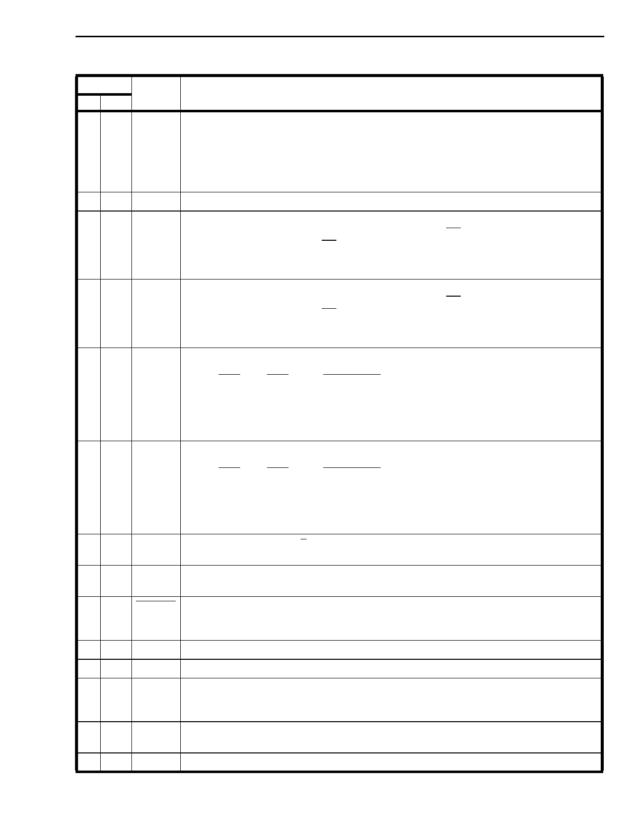
Pin Description (continued)
Pin #
Name
DIP PLCC
Description
6 7 BCLK Bit Clock input for both PCM and ADPCM ports; used in SSI mode only. The falling edge of
this clock is used to clock data in on DSTi and ADPCMi. The rising edge is used to clock
data out on DSTo and ADPCMo. Can be any rate between 128 kHz and 2.048 MHz. Refer
to the serial timing diagrams of Figures 12 and 13. When not used, this pin should be tied
to VSS.
This is a TTL level input.
78
VSS Power supply ground (0 volts).
8 10 ENB2 Enable Strobe input for B2 channel PCM timing in SSI mode only. A valid 8-bit strobe must
be present at this input if there are no ST-BUS signals at F0i and MCLK. When the device
detects a valid frame pulse at F0i, PCM timing for the B2 ST-BUS channel is decoded
internally and the ENB2 input is ignored. When not used this pin should be tied to VSS.
This is a TTL level input.
9 11 ENB1 Enable Strobe input for B1 channel PCM timing in SSI mode only. A valid 8-bit strobe must
be present at this input if there are no ST-BUS signals at F0i and MCLK. When the device
detects a valid frame pulse at F0i, PCM timing for the B1 ST-BUS channel is decoded
internally and the ENB1 input is ignored. When not used this pin should be tied to VSS.
This is a TTL level input.
10, 12,
11 13
MS1,
MS2
Mode select control input pins 1 and 2 for the B1 channel according to the following:
MS2 MS1
B1 Channel
0
0
algorithm reset
0
1
ADPCM bypass mode (24 or 32 kbit/s)
1
0
24 kbit/s ADPCM mode
1
1
32 kbit/s ADPCM mode
These are TTL level inputs.
12, 14,
13 16
MS3,
MS4
Mode select control input pins 3 and 4 for the B2 channel according to the following:
MS4 MS3
B2 Channel
0
0
algorithm reset
0
1
ADPCM bypass mode (24 or 32 kbit/s)
1
0
24 kbit/s ADPCM mode
1
1
32 kbit/s ADPCM mode
These are TTL level inputs.
14 17
A/µ Law select input. Selects µ-Law when low, A-Law when high.
This is a TTL level input.
15 18 FORMAT Format select input. Selects CCITT PCM coding if high, or SIGN MAGNITUDE PCM if low.
This is a TTL level input.
16 19 PWRDN Power Down input. Logic low on this pin forces the device to assume an internal power
down mode where all operation is halted. This mode minimizes power consumption.
Outputs are tri-stated. This is a schmidt trigger input.
17 20
18 22
19 23
IC
VDD
ENA
Internal Connection. Tie to VSS for normal operation.
Positive power supply input, 5 volts ± 10%.
Enable Strobe input for both input and output ADPCM channels; used for SSI operation
only. Refer to Figure 3. When not used, tie to VSS.
This is a TTL level input.
20 24 ADPCMi Serial ADPCM word input data stream. Refer to the serial timing diagram of Fig. 13. This is
a TTL level input.
21 25 ADPCMo Serial ADPCM word output stream. Refer to the serial timing diagram of Fig.13.
8-75
Share Link: 