TQ5631 데이터 시트보기 (PDF) - TriQuint Semiconductor
부품명
상세내역
제조사
TQ5631 Datasheet PDF : 14 Pages
| |||
Verification of Proper LO Buffer Amp Tuning
Using a Network Analyzer
Connect port 1 to the L0 input (Pin 5) of the TQ5631 with the
source power set to deliver -4 dBm. Connect the coaxial probe
to Port 2 and place the probe tip approximately 0.1 inch away
from the inductor. The magnitude of S21 represents the L0
buffer frequency response (figure 3). The test can be done in
any of the CDMA modes, but both the rf and IF ports should be
terminated to 50 ohms.
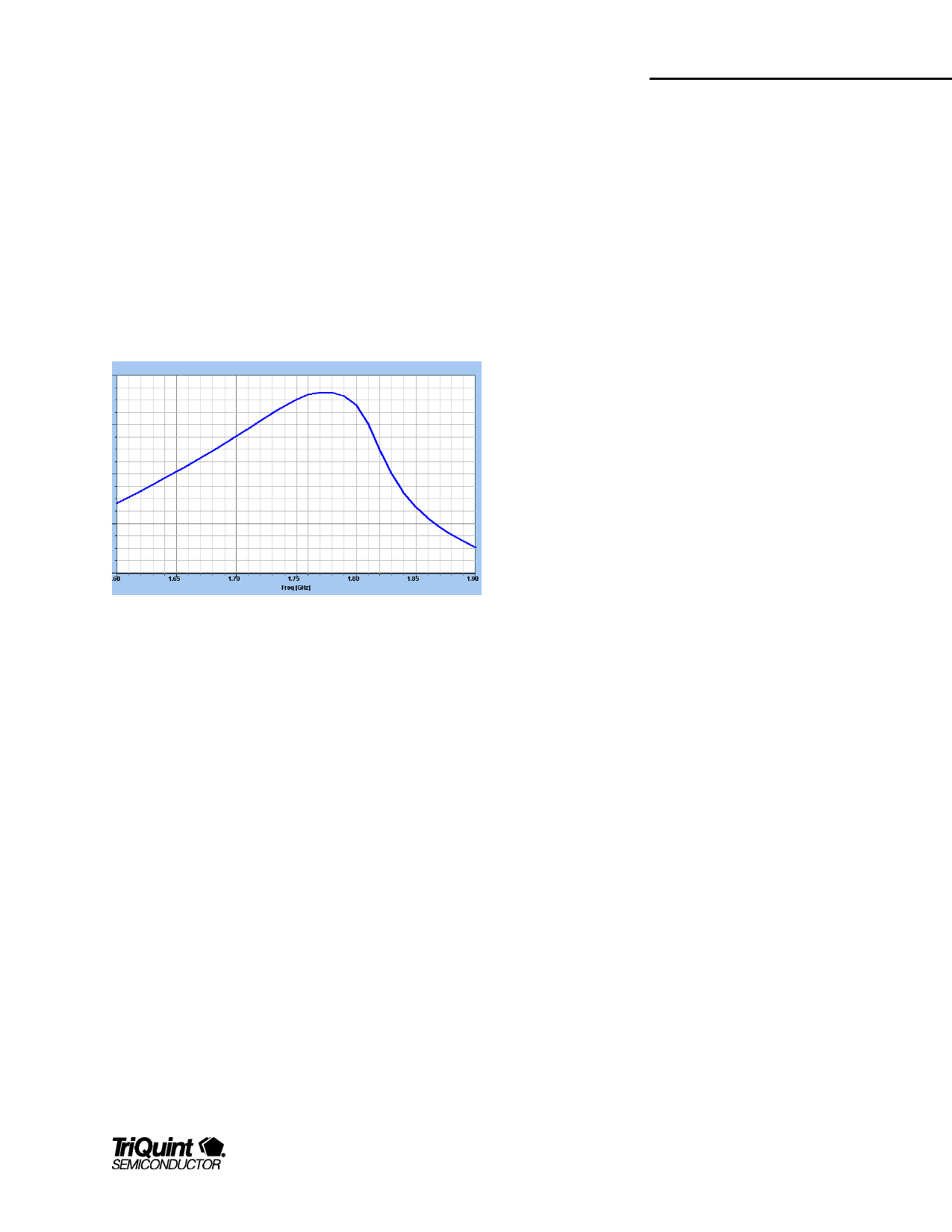
Figure 3 LO Buffer Response
The absolute value isn't important, since it depends on the
probe's distance from the pin (it is usually around -30 dB), but
the peak of the response should be centered in the slightly to
the right of the L0 frequency band center, in this case 1750Mhz.
Increasing the inductance will lower the center frequency, and
vice versa. Try to keep the probe away from the LO input as it
will interfere with the measurement.
We have found experimentally that optimum mixer performance
is achieved when the LO is tuned slightly higher than the band
center. Additionally, since the curve is much steeper on the
high-side of the LO tuning curve, it is best to tune the device to a
slightly higher frequency to ensure that the application is never
operated in that region of the curve. Small variations in the
application circuit due to inductor tolerances and pc board trace
capacitance will then have less affect on the circuit.
Lower than expected IIP3 is the major symptom of improper LO
tuning in an application. The internal passive mixer FET needs
some minimum LO voltage at its gate in order to achieve
satisfactory IP3, which does not occur if the LO is untuned.
TQ5631
Data Sheet
Half IF Spur Rejection Considerations
Because the TQ5631 does not contain a balanced mixer, Half IF
spur rejection is completely set by the image filter. Thus we do
not recommend using an IF that is less than 2.5 times the
bandwidth of the image filter.
Downconverter IF Match Design
The Mixer IF output (pin 3) is an "open-drain" configuration,
allowing for flexibility in efficient matching to various filter types
and at various IF frequencies. An optimum lumped-element
matching network must be designed for maximum power gain
and output third order intercept.
When designing the IF output matching circuit, one has to
consider the output impedance (pin 3) of the IF Amplifier. It will
vary somewhat depending on the quiescent current, which is set
with the GIC pin. The IF frequency can be tuned from 100 to
300 MHz by varying component values of the IF output
matching circuit. The IF output pin also provides the DC bias for
the output FET’s.
In the user's application, the IF output is most commonly
connected to a narrowband SAW or crystal filter with impedance
from 300 -1000Ω with 1 - 2 pF of capacitance. A conjugate
match to a higher filter impedance is generally less sensitive
than matching to 50Ω. When verifying or adjusting the matching
circuit on the prototype circuit board, the LO drive should be
injected at the nominal power level (-4 dBm), since the LO level
does have an impact on the IF port impedance.
Suggested Matching Networks
There are several networks that can be used to properly match
the IF port to the SAW or crystal IF filter. The IF FET current is
applied through the IF output pin 3, so the matching circuit
topology must contain either an RF choke or shunt inductor as
shown in Figure 4.
For purposes of evaluation, the shunt L, series C, shunt C circuit
shown below is the simplest and requires the fewest
components. DC current can be easily injected through the
shunt inductor and the series C provides a DC block, if needed.
The shunt C, in particular can be used to improve the return loss
and to reduce the LO leakage. Generally the shunt C should be
equal or larger than the series C. Furthermore, for best stability,
For additional information and latest specifications, see our website: www.triquint.com
9
Share Link: 