NJM3775E3 데이터 시트보기 (PDF) - Japan Radio Corporation
부품명
상세내역
제조사
NJM3775E3 Datasheet PDF : 10 Pages
| |||
NJM3775
s FUNCTIONAL DESCRIPTION
Each channel of the NJM3775 consists of the following sections: an output H-bridge with four transistors and four
recirculation diodes, capable of driving up to 750 mA continuous current to the motor winding,
a logic section that controls the output transistors, an S-R flip-flop, and a com- parator. The clock-oscillator is
common
to both channels.
Constant current control is achieved by switching the output current to the windings. This is done by sensing the
peak current through the winding via a current-sensing resistor RS, effectively connected in series with the motor
winding. As the current increases, a voltage develops across the sensing resistor, which is fed back to the compa-
rator. At the predetermined level, defined by the voltage at the reference input V , the comparator resets the flip-
R
flop, which turns off the upper output transistor. The turn-off of one channel is independent of the other channel.
The current decreases until the clock oscillator triggers the flip-flops of both channels simultaneously, which turns
on the output transistors again, and the cycle is repeated.
To prevent erroneous switching due to switching transients at turn-on, the
NJM3775 includes a digital filter. The clock oscillator provides a blanking pulse which is used for digital filtering of
the voltage transient across the current sensing resistor during turn-on.
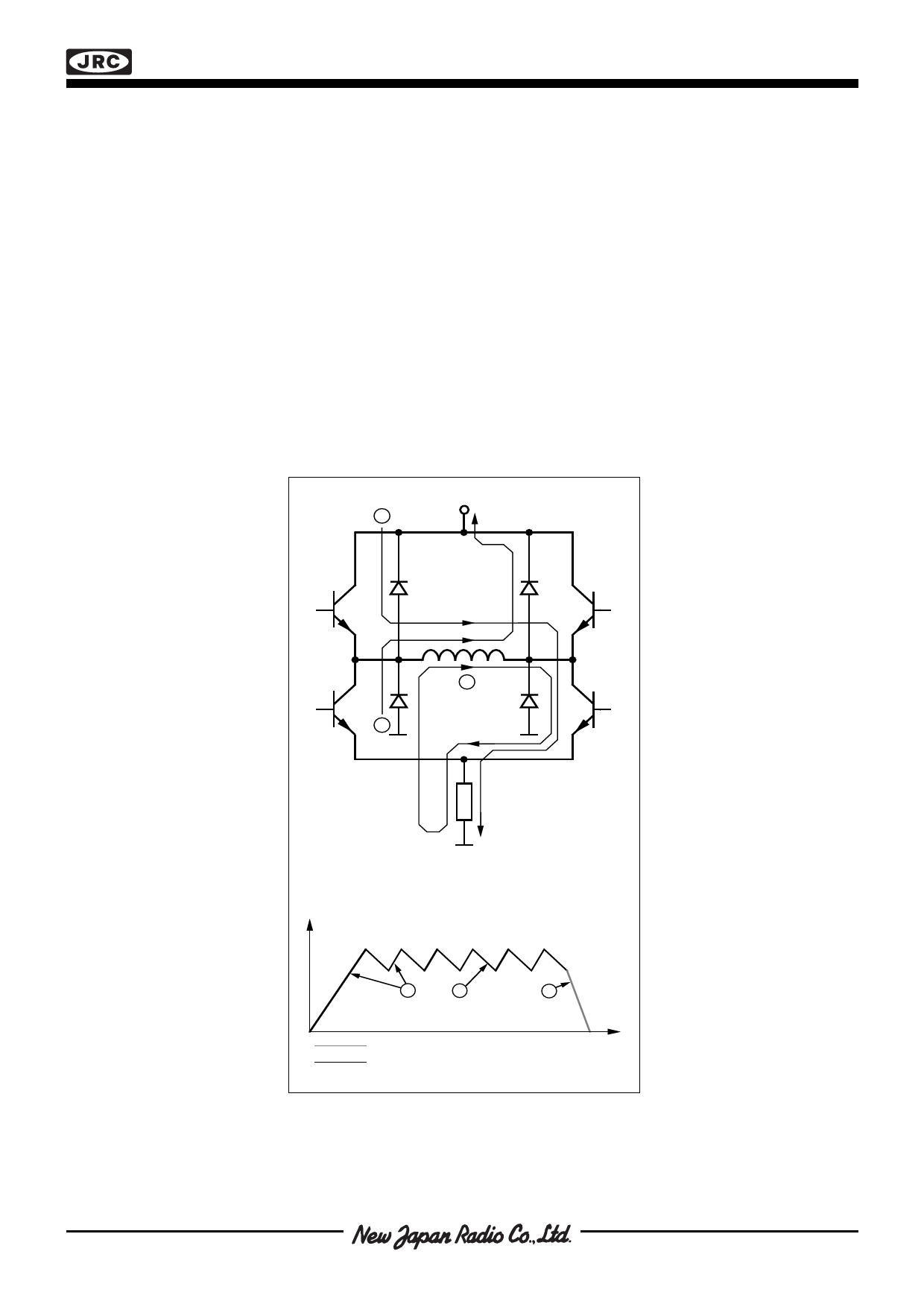
The current paths during turn-on, turn-off and phase shift are shown in figure 3.
V MM
1
2
3
RS
Motor Current
1
2
3
Fast Current Decay
Slow Current Decay
Time
Figure 3. Output stage with current paths
during turn-on, turn-off and phase shift.
Share Link: 