NJM3774 데이터 시트보기 (PDF) - Japan Radio Corporation
부품명
상세내역
제조사
NJM3774 Datasheet PDF : 9 Pages
| |||
NJM3774
s FUNCTIONAL DESCRIPTION
Each channel of the NJM3774 consists of the following sections: an output H-bridge with four transistors, capable
of driving up to 1000mA continuous current to the motor winding; a logic section that controls the output transistors;
an S-R flip-flop; and a comparator. The clock-oscillator is common to both channels.
Constant current control is achieved by switching the output current to the windings. This is done by sensing the
peak current through the winding via a resistor, RS, effectively connected in series with the motor winding during the
turn-on period. As the current increases, a voltage develops across the resistor, and is fed back to the comparator.
At the predetermined level defined by the voltage at the reference input VR, the comparator resets the flip-flop,
turning off the output transistors. The current decreases until the clock oscillator triggers the flip-flop, turning on the
output transistors, and the cycle is repeated.
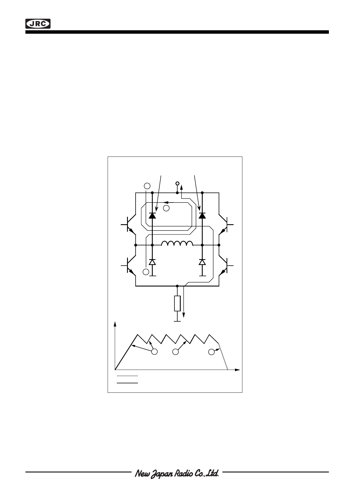
The current paths during turn-on, turn-off and phase shift are shown in figure 3. Note that the upper recirculation
diodes are connected to the circuit externally.
External recirculation diodes
1
VMM
2
3
RS
Motor Current
1
2
3
Fast Current Decay
Slow Current Decay
Time
Figure 3. Output stage with current paths
during turn-on, turn-off and phase shift.
Share Link: 