MC10189 데이터 시트보기 (PDF) - ON Semiconductor
부품명
상세내역
제조사
MC10189 Datasheet PDF : 4 Pages
| |||
MC10189
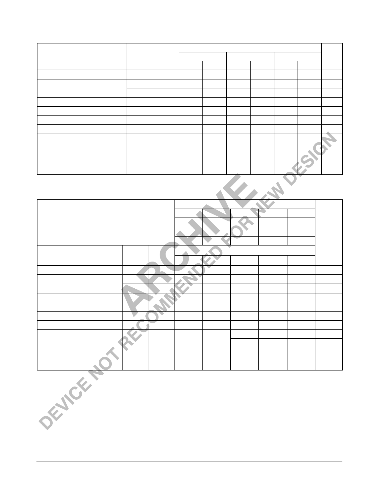
ELECTRICAL CHARACTERISTICS
Characteristic
Power Supply Drain Current
Input Current
Output Voltage
Output Voltage
Threshold Voltage
Threshold Voltage
Switching Times
Propagation Delay
Rise/Fall Time
Logic 1
Logic 0
Logic 1
Logic 0
(50Ω Load)
Enable
Data
(20 to 80%)
Symbol
IE
IinH
IinL
VOH
VOL
VOHA
VOLA
tPHL
tPLH
tTLH
tTHL
Pin
Under
Test
8
5
9
2
2
2
2
2
2
2
–30°C
Min
Max
44
425
890
–1.060 –0.890
–1.890 –1.675
–1.080
–1.655
1.1
3.9
1.0
3.3
Test Limits
+25°C
Min
Max
40
265
555
–0.960 –0.810
–1.850 –1.650
–0.980
–1.630
1.1
3.5
1.0
2.9
+85°C
Min
Max
44
265
555
–0.890 –0.700
–1.825 –1.615
–0.910
–1.595
1.1
3.9
1.0
3.3
Unit
mAdc
µAdc
µAdc
Vdc
Vdc
Vdc
Vdc
ns
1.1
3.7
1.1
3.3
1.1
3.7
ELECTRICAL CHARACTERISTICS (continued)
TEST VOLTAGE VALUES (Volts)
@ Test Temperature
–30°C
VIHmax
–0.890
VILmin
–1.890
VIHAmin
–1.205
VILAmax
–1.500
VEE
–5.2
+25°C –0.810
–1.850
–1.105
–1.475
–5.2
+85°C –0.700
–1.825
–1.035
–1.440
–5.2
Characteristic
Power Supply Drain Current
Input Current
Output Voltage
Output Voltage
Threshold Voltage
Threshold Voltage
Switching Times
Logic 1
Logic 0
Logic 1
Logic 0
(50Ω Load)
Symbol
IE
IinH
IinL
VOH
VOL
VOHA
VOLA
Pin
Under
Test
8
5
9
2
2
2
2
TEST VOLTAGE APPLIED TO PINS LISTED BELOW
VIHmax
VILmin
VIHAmin
VILAmax
VEE
8
5
8
9
8
5
9
8
8
5
8
5
Pulse In Pulse Out
8
–3.2 V
(VCC)
Gnd
1, 16
1, 16
1, 16
1, 16
1, 16
1, 16
1, 16
+2.0 V
Propagation Delay
Enable tPHL
2
Data tPLH
2
9
2
8
1, 16
5
2
8
1, 16
Rise/Fall Time
(20 to 80%) tTLH
tTHL
2
5
2
8
1, 16
Each MECL 10,000 series circuit has been designed to meet the dc specifications shown in the test table, after thermal equilibrium has been
established. The circuit is in a test socket or mounted on a printed circuit board and transverse air flow greater than 500 linear fpm is maintained.
Outputs are terminated through a 50–ohm resistor to –2.0 volts. Test procedures are shown for only one gate. The other gates are tested in the
same manner.
http://onsemi.com
2
Share Link: 