L5971 데이터 시트보기 (PDF) - STMicroelectronics
부품명
상세내역
제조사
L5971 Datasheet PDF : 11 Pages
| |||
L5971
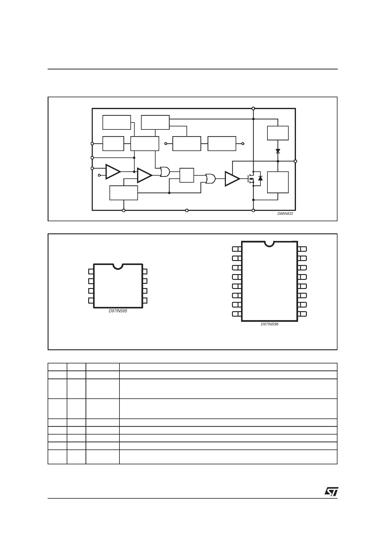
BLOCK DIAGRAM
THERMAL
SHUTDOWN
VOLTAGES
MONITOR
2
SS_INH
INHIBIT
7
COMP
8
E/A
FB
1.26V
SOFTSTART
1.26V
INTERNAL
REFERENCE
PWM
R
Q
S
OSCILLATOR
3
OSC
1
GND
PIN CONNECTIONS
VCC
5
INTERNAL
SUPPLY 5.1V
DRIVE
CBOOT
CHARGE
6
BOOT
CBOOT
CHARGE
AT LIGHT
LOADS
4
OUT
D98IN833
GND
SS_INH
OSC
OUT
1
8
2
7
3
6
4
5
D97IN595
FB
COMP
BOOT
VCC
Minidip
N.C.
GND
SS_INH
OSC
OUT
OUT
N.C.
N.C.
1
16
2
15
3
14
4
13
5
12
6
11
7
10
8
9
D97IN596
SO16W
N.C.
N.C.
FB
COMP
BOOT
VCC
N.C.
N.C.
PIN FUNCTIONS
DIP SO (*)
1
2
2
3
Name
GND
SS_INH
3
4
OSC
4 5, 6
OUT
5
11
VCC
6
12
BOOT
7
13
COMP
8
14
FB
Function
Ground
A logic signal (active low) disables the device (sleep mode operation).
A capacitor connected between this pin and ground determines the soft start time.
When this pin is grounded disables the device (driven by open collector/drain).
An external resistor connected between the unregulated input voltage and this pin and
a capacitor connected from this pin to ground fix the switching frequency. (Line feed
forward is automatically obtained)
Stepdown regulator output
Not regulated DC input voltage
A capacitor connected between this pin and OUT allows to drive the internal VDMOS
E/A output to be used for frequency compensation
Stepdown feedback input. Connecting directly this pin to the output 1.26V is obtained; a
voltage divider is requested for higher output voltages
(*) Pins 1, 7, 8, 9, 10, 15 and 16 are not internally, electrically connected to the die.
2/11
Share Link: 