M64898GP 데이터 시트보기 (PDF) - MITSUBISHI ELECTRIC
부품명
상세내역
제조사
M64898GP Datasheet PDF : 8 Pages
| |||
MITSUBISHI ICs (TV)
M64898GP
PLL FREQUENCY SYNTHESIZER WITH DC-DC CONVERTER FOR PC
METHOD OF SETTING DATA
The programmable divider ratio uses 15bits. Setting up the band
switching output uses 4bits.
The test mode data uses 8bits. The total bits used is 27bits. Data is
read in when the enable signal is "H" and the clock signal falls.
The band switching data is read in at the 4th pulse of the clock
signal. The programmable counter data is read into the latch by the
fall of the enable signal after the 18th pulse of the clock signal or the
fall of the 19th pulse of the clock signal. When the enable signal
goes to "L" before the 18th pulse of the enable signal, only the band
SW data is updated and other data is ignored.
Automatic judgment facility comes being it, and, as for Shift resister,
CONT terminal rises by 18/19 bits at the time of "L". At the time of
data of 18 bits, M9 bit of Programable divider is done reset of, and
it is established in reference frequency divider ratio 1/512.
At the time of 19 bits,reference frequency divider ratio is established
in 1/1024.
When reference frequency divider ratio was established in 1/640 by
19 bits at the time of "opening" CONT terminal, and it became "L"
before 19 pulse enable signal, only band SW data are renewed, and
other data are ignored.
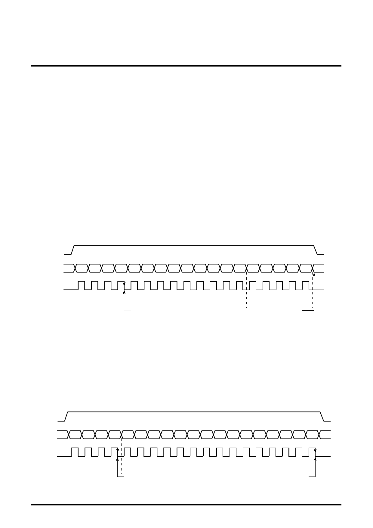
(1) Transfer of the 18th bit data (CONT terminal is "L" )
Data is latched by the fall of the enable signal after the 18th clock
signal. At this time, the divider of the 1/512 of the reference
frequency is used.
ENA
DATA
CLK
BS4 BS3 BS2 BS1 28 27 26 25 24 23 22 21 20 24 23 22 21 20
M8 M7 M6 M5 M4 M3 M2 M1 M0 S4 S3 S2 S1 S0
BAND SW
DATA
M COUNTER DIVIDER
RATIO SETTING
READ INTO LATCH
S COUNTER DIVIDER
RATIO SETTING
READ INTO LATCH
(2) Transfer of the 19th bit data (CONT terminal is "L" or "open")
The data is latched at the 19th pulse of the clock signal.
Reference frequency divider ratio is established in 1/1024 in case of
"L" CONT terminal at this time.
Reference frequency divider ratio is established in 1/640 in case of
"opening" CONT terminal.
Invalid the clock signal after 19th pulse.
Notice) When CONT terminal is "L", to change reference frequency,
set up as ENA in "L" after 19th pulse of clock signal by all means.
ENA
DATA
CLK
BS4 BS3 BS2 BS1 29 28 27 26 25 24 23 22 21 20 24 23 22 21 20
M9 M8 M7 M6 M5 M4 M3 M2 M1 M0 S4 S3 S2 S1 S0
BAND SW
DATA
M COUNTER DIVIDER
RATIO SETTING
READ INTO LATCH
S COUNTER DIVIDER
RATIO SETTING
READ INTO LATCH
5
Share Link: 