MP7720 데이터 시트보기 (PDF) - Monolithic Power Systems
부품명
상세내역
제조사
MP7720 Datasheet PDF : 11 Pages
| |||
MP7720 – 20W CLASS D MONO SINGLE ENDED AUDIO AMPLIFIER
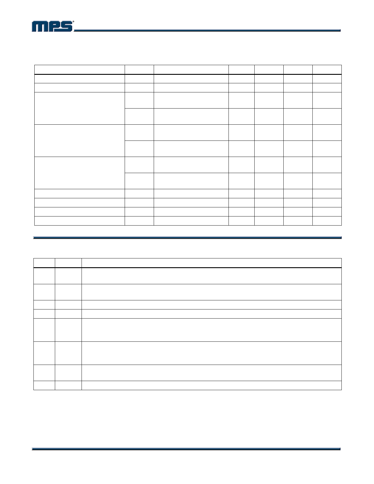
OPERATING SPECIFICATIONS
Circuit of Figure 1, VDD = 24V, VEN = 5V, TA = +25°C, unless otherwise noted.
Parameters
Symbol Condition
Min
Typ
Standby Current
VEN = 0V
130
Quiescent Current
13
Power Output
f = 1KHz, THD+N = 10%,
4Ω Load
20
f = 1KHz, THD+N = 10%,
8Ω Load
10
THD+ Noise
POUT = 1W, f = 1KHz, 4Ω
Load
POUT = 1W, f = 1KHz, 8Ω
Load
0.08
0.04
Efficiency
f = 1KHz, POUT = 1W, 4Ω
Load
90
f = 1KHz, POUT = 1W, 8Ω
Load
95
Maximum Power Bandwidth
20
Dynamic Range
93
Noise Floor
A-Weighted
190
Power Supply Rejection
f = 1KHz
60
Max Units
µA
mA
W
W
%
%
%
%
KHz
dB
µV
dB
PIN FUNCTIONS
Pin # Name Description
1
PIN
Amplifier Positive Input. PIN is the positive side of the differential input to the amplifier. Use a
resistive voltage divider to set the voltage at PIN to VDD/2. See Figure 1.
2
NIN
Amplifier Negative Input. NIN is the negative side of the differential input to the amplifier. Drive
the input signal and close the feedback loop at NIN. See Figure 1.
3 AGND Analog Ground. Connect AGND to PGND at a single point.
4
EN Enable Input. Drive EN high to turn on the amplifier, low to turn it off.
High-Side MOSFET Bootstrap Input. A capacitor from BS to SW supplies the gate drive
5
BS current to the internal high-side MOSFET. Connect a 0.1µF capacitor from SW to BS. Place a
6.2V zener diode from BS to SW to prevent overstressing of the internal circuitry.
Power Supply Input. VDD is the drain of the high-side MOSFET switch, and supplies the
6
VDD power to the output stage and the MP7720 internal control circuitry. In addition to the main
bulk capacitor, bypass VDD to PGND with a 1µF X7R capacitor placed close to pins 6 and 8.
7
SW
Switched Power Output. SW is the output of the MP7720. Connect the LC filter between SW
and the output coupling capacitor. See Figure 1.
8 PGND Power Ground. Connect PGND to AGND at a single point.
MP7720 Rev. 1.9
www.MonolithicPower.com
3
3/13/2006
MPS Proprietary Information. Unauthorized Photocopy and Duplication Prohibited.
© 2006 MPS. All Rights Reserved.
Share Link: 