ST14C02 데이터 시트보기 (PDF) - STMicroelectronics
부품명
상세내역
제조사
ST14C02 Datasheet PDF : 12 Pages
| |||
ST14C02C
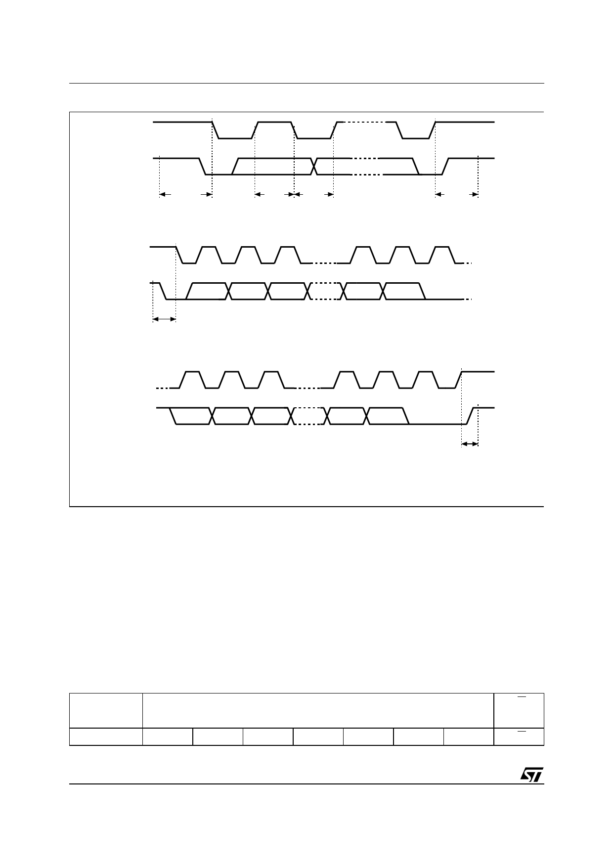
Figure 5. I2C Bus Protocol
SCL
SDA
START
CONDITION
SDA
SDA
INPUT CHANGE
STOP
CONDITION
SCL
SDA
1
2
3
MSB
START
CONDITION
7
8
9
ACK
SCL
SDA
1
2
3
MSB
7
8
9
ACK
STOP
CONDITION
AI00792
Start Condition
START is identified by a high to low transition of
the SDA line while the clock, SCL, is stable in the
high state. A START condition must precede any
data transfer command. The memory continuously
monitors (except during a programming cycle) the
SDA and SCL lines for a START condition, and will
not respond unless one is given.
Stop Condition
STOP is identified by a low to high transition of the
SDA line while the clock SCL is stable in the high
state. A STOP condition terminates communica-
tion between the memory and the bus master. A
STOP condition at the end of a Read command
forces the memory device into its standby state. A
STOP condition at the end of a Write command
triggers the internal EEPROM write cycle.
Acknowledge Bit (ACK)
An acknowledge signal is used to indicate a suc-
cessful data transfer. The bus transmitter, either
master or slave, will release the SDA bus after
sending 8 bits of data. During the 9th clock pulse
Table 4. Device Select Code 1
Device Code
RW
b7
b6
b5
b4
b3
b2
b1
b0
Device Select
1
0
1
0
0
0
0
RW
Note: 1. The most significant bit, b7, is sent first.
4/12
Share Link: 