PS2832-1-V 데이터 시트보기 (PDF) - Renesas Electronics
부품명
상세내역
제조사
PS2832-1-V Datasheet PDF : 16 Pages
| |||
PS2832-1,-4,PS2833-1,-4
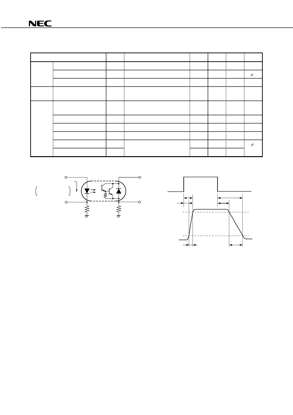
ELECTRICAL CHARACTERISTICS (TA = 25°C)
Parameter
Symbol
Conditions
MIN. TYP. MAX. Unit
Diode
Forward Voltage
Reverse Current
VF
IF = 10 mA
IR
VR = 5 V
1.2
1.4
V
5
μA
Terminal Capacitance
Ct V = 0 V, f = 1 MHz
15
pF
Transistor Collector to Emitter Dark
Current
ICEO IF = 0 mA, VCE = 300 V
400
nA
Coupled
Current Transfer Ratio
(IC/IF)
CTR IF = 1 mA, VCE = 2 V
400 2 000 4 500
%
Collector Saturation Voltage
Isolation Resistance
VCE (sat)
RI-O
IF = 1 mA, IC = 2 mA
VI-O = 1 kVDC
1.0
V
1011
Ω
Isolation Capacitance
CI-O V = 0 V, f = 1 MHz
0.4
pF
Rise Time*1
tr
VCC = 5 V, IC = 10 mA, RL = 100 Ω
20
μs
Fall Time*1
tf
5
<R>
*1 Test circuit for switching time
Pulse Input
PW = 1 ms
Duty cycle = 1/10
In monitor
IF
50 Ω
VCC
Input
VOUT
RL = 100 Ω
Output
ton
td
tr
toff
ts
90%
10%
tf
Data Sheet PN10257EJ03V0DS
5
Share Link: 