LX6431BCPK 데이터 시트보기 (PDF) - Microsemi Corporation
부품명
상세내역
제조사
LX6431BCPK Datasheet PDF : 11 Pages
| |||
THE INFINITE POWER OF INNOVATION
LX6431 / 6431A / 6431B
PRECISION PROGRAMMABLE REFERENCES
PRODUCTION DATA SHEET
ABSOLUTE MAXIMUM RATINGS
Cathode to Anode Voltage (VKA).................................................................... -0.3V to 37V
Reference Input Current (IREF) .....................................................................-50µA to 10µA
Continuous Cathode Current (IK)........................................................... -100mA to 150mA
Operating Temperature Range ................................................................................... 150°C
Maximum Operating Junction Temperature
Plastic (DM & LP Packages) ..................................................................................... 150°C
Storage Temperature Range.........................................................................-65°C to 150°C
Package Peak Temp. for Solder Reflow (40 seconds maximum exposure) ... 260°C (+0 -5)
Note: Exceeding these ratings could cause damage to the device. All voltages are with respect to
Ground. Currents are positive into, negative out of specified terminal.
Pin numbers refer to DIL packages only.
THERMAL DATA
DM Plastic SOIC 8-Pin
THERMAL RESISTANCE-JUNCTION TO AMBIENT, θJA
165°C/W
PACKAGE PIN OUT
CATHODE
N.C.
ANODE
N.C.
1
8
2
7
3
6
4
5
DM PACKAGE
(Top View)
REF
ANODE
ANODE
N.C.
1 CATHODE
2 ANODE
3 REF
LP PACKAGE
(Top View)
REF
1
LP Plastic TO-92 3-Pin
THERMAL RESISTANCE-JUNCTION TO AMBIENT, θJA
156°C/W
PK Plastic TO-89 3-Pin
THERMALRESISTANCE-JUNCTION TO TAB, θJT
THERMAL RESISTANCE-JUNCTION TO AMBIENT, θJA
35°C/W
71°C/W
Junction Temperature Calculation: TJ = TA + (PD x θJA).
The θJA numbers are guidelines for the thermal performance of the device/pc-board system. All of the
above assume no ambient airflow.
ANODE
2
CATHODE
3
PK PACKAGE
(Top View)
N.C. – No Connection
RoHS / Pb-free 100% Matte Tin Lead Finish
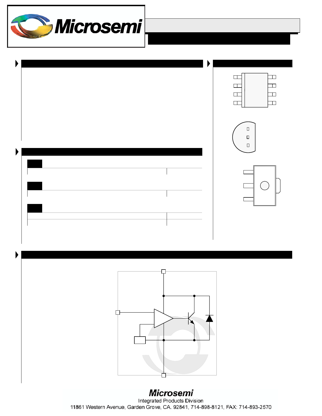
SIMPLIFIED BLOCK DIAGRAM
Cathode (K)
REF(R)
+
-
VREF
Anode (A)
Copyright © 1999
Rev. 1.4a,2005-04-04
LINFINITY MICROELECTRONICS INC.
11861 WESTERN AVENUE, GARDEN GROVE, CA. 92841, 714-898-8121, FAX: 714-893-2570
2
Share Link: 