45LM 데이터 시트보기 (PDF) - Unspecified
부품명
상세내역
제조사
45LM Datasheet PDF : 6 Pages
| |||
45LM Series Modules
Removing and Installing the Plug-In Modules
CAUTION . . .
Electrical Shock Hazard
An electrical shock hazard
exists inside the sensor
whenever power is applied.
Remove all power to the sensor (and
to the load) whenever the transparent
top cover will be raised and the black
inside cover will be removed.
Failure to remove power while these
covers are removed could result in injury.
NOTE: It is not necessary to remove
power simply to adjust the
Sensitivity or Timing controls,
as long as the black inside cover
remains in place.
To remove or install any of the 45LM modules (done through the top of the sensor),
perform the following steps:
1) Remove all power from the sensor and load.
2) Loosen the top cover hold-down screw and raise the transparent cover
(it is hinged).
3) Insert a small screwdriver into one of the slots at the front of the black inner
cover, lift and remove (Figure 5).
4) Insert a small screwdriver into one of the slots at the side of the module to be
removed and pry it up until you can grasp it with your fingers and remove
(Figure 6).
5) Press the new module into place (Figure 7).
6) Replace the black cover, then the transparent hinged cover, and tighten the
hold-down screw.
7) Reapply power as desired.
NOTE: If only installing a new module (and not removing an old one), skip step 4.
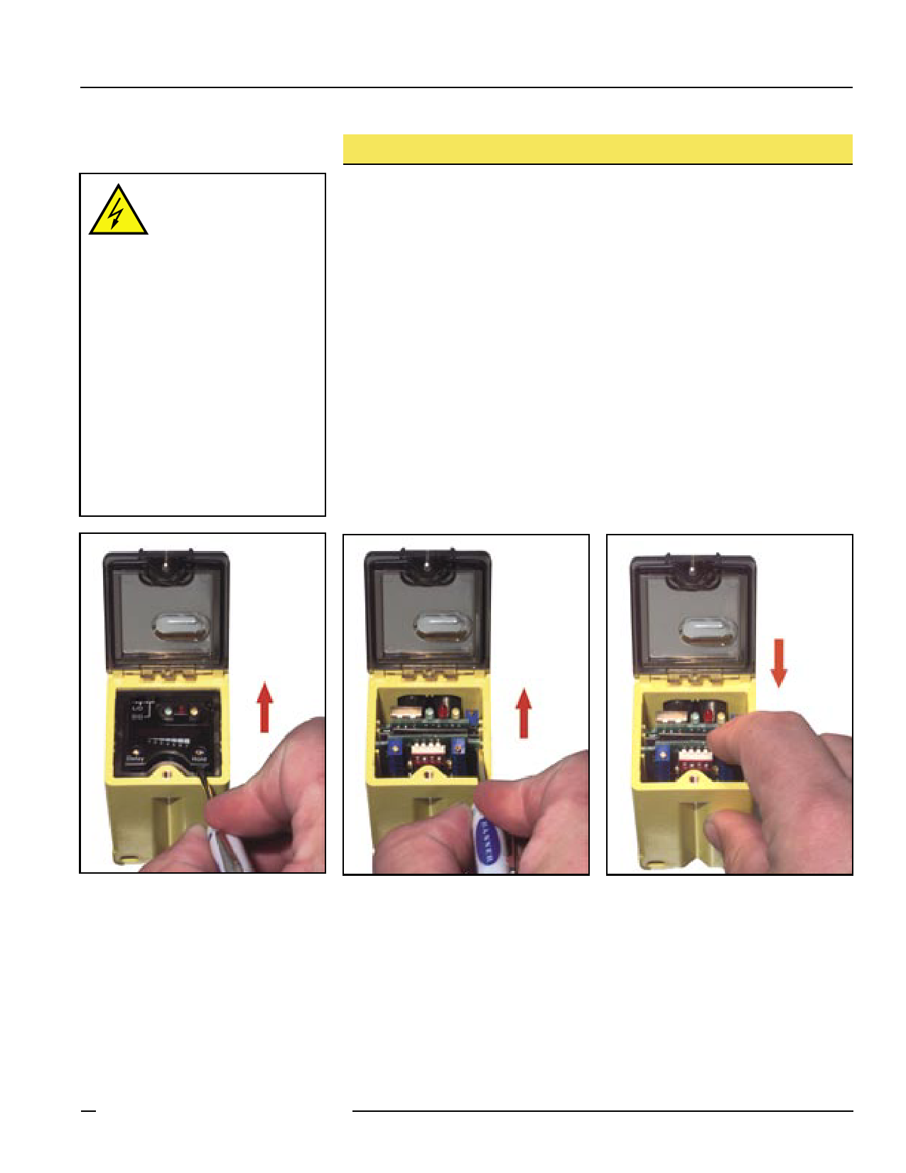
Figure 5. Insert a small screwdriver into
the slot and lift the black cover to
remove.
Figure 6. Using the small screwdriver in
the module slot if necessary
to nudge the module loose, lift
the module up and out.
Figure 7. Slide the new module into place,
pressing until it fits snugly.
Banner Engineering Corp. • Minneapolis, MN U.S.A.
www.bannerengineering.com • Tel: 763.544.3164
p/n 634P1/N663R41e6vr.evB. A 5
Share Link: 