LT1635 데이터 시트보기 (PDF) - Linear Technology
부품명
상세내역
제조사
LT1635 Datasheet PDF : 12 Pages
| |||
LT1635
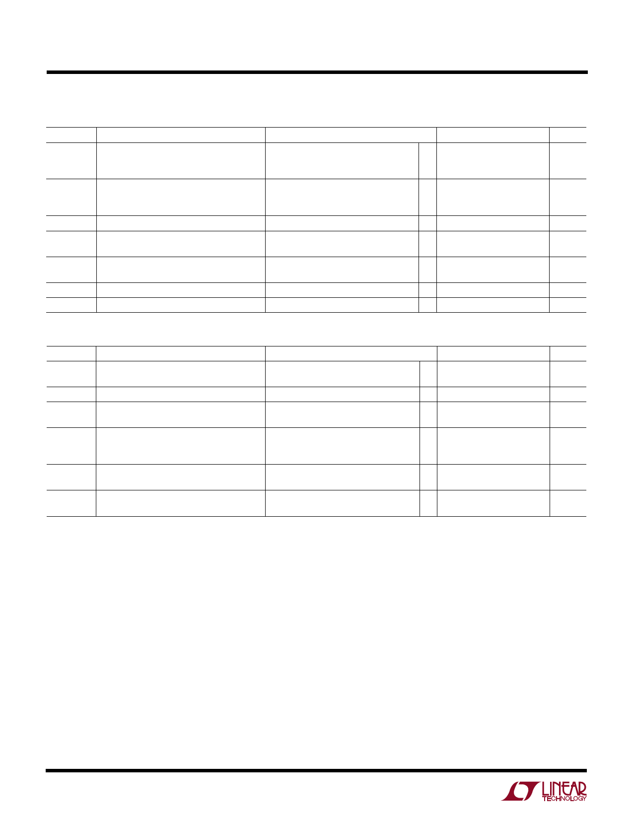
ELECTRICAL CHARACTERISTICS
±5V OP AMP: VS = ±5V; VCM = VOUT = 0V, TA = 25°C, unless otherwise noted. (Note 1)
SYMBOL
PARAMETER
CONDITIONS
AVOL
VO
ISC
PSRR
Large-Signal Voltage Gain
Output Voltage Swing
Short-Circuit Current
Power Supply Rejection Ratio
VO = – 4.5V to 4.5V, No Load
VO = – 4.5V to 4.5V, RL = 1.1k
VO = – 4.5V to 4.5V, RL = 500Ω
VS = ±5V, No Load
VS = ±5V, ISINK = 5mA
VS = ±5V, ISINK = 10mA
VS = ±5V
VS = ±1V to ±6V, VCM = VO = 0V
IS
Supply Current
GBW
Gain Bandwidth Product
SR
Slew Rate
f = 1kHz
AV = –1, RL = ∞
MIN TYP MAX
q 175
300
q
15
100
q 10
60
q ±4.975 ±4.985
q ±4.65 ±4.75
q ±4.5 ±4.6
±25 ±40
90
100
q 88
98
135 215
q
160
280
175
0.05
UNITS
V/mV
V/mV
V/mV
mV
mV
mV
mA
dB
dB
µA
µA
kHz
V/µs
±5V REFERENCE: VS = ±5V, TA = 25°C, unless otherwise noted. (Note 1)
SYMBOL
PARAMETER
CONDITIONS
VREF
Feedback Sense Voltage
Voltage at Pin 1 with Pin 1 Connected
to Pin 8 (Note 5)
TC VREF
Reference Drift
Feedback Current
(Note 3)
Current into Pin 8
Line Regulation
Load Regulation
Reference Amplifier Gain
0 ≤ IREF ≤ 1mA, VREF = 200mV
VS = ±0.6V to ±5V
VS = ±0.65V to ±5V (Note 2)
IREF = 0 to 1mA
VO = 0.2V to 8.5V
VS = 10V, 0V
MIN
q 189
q
q
q
q
45
q 25
TYP MAX
200 211
UNITS
mV
40
120 ppm/°C
3.5
10
nA
5.0
15
nA
20
25
ppm /V
30
55
ppm / V
150 300 ppm/mA
200 500 ppm/mA
90
V/mV
50
V/mV
The q denotes specifications that apply over the full operating temperature
range.
Note 1: The LT1635C is guaranteed to operate over the commercial
temperature range of 0°C to 70°C. It is designed, characterized and
expected to meet these extended temperature limits, but is not tested at
– 40°C and 85°C. The LT1635I is guaranteed to meet the industrial
temperature range.
Note 2: The LT1635 op amp operates on a 1.2V supply over the full
industrial temperature range with an input common mode of 0V to 0.2V.
The minimum supply voltage for the reference to operate properly over
this temperature range is 1.3V.
Note 3: This parameter is not 100% tested. Temperature coefficient is
measured by dividing the change in output voltage by specified
temperature range.
Note 4: Shunt gain defines the operation in floating applications when the
output is connected to the V + terminal and input common mode is
referred to V –.
Note 5: If part is stored outside of the specified temperature range, the
output may shift due to hysteresis.
4
Share Link: 