M56785FP 데이터 시트보기 (PDF) - MITSUBISHI ELECTRIC
부품명
상세내역
제조사
M56785FP Datasheet PDF : 11 Pages
| |||
MITSUBISHI <CONTROL / DRIVER IC>
M56785FP
SPINDLE MOTOR DRIVER
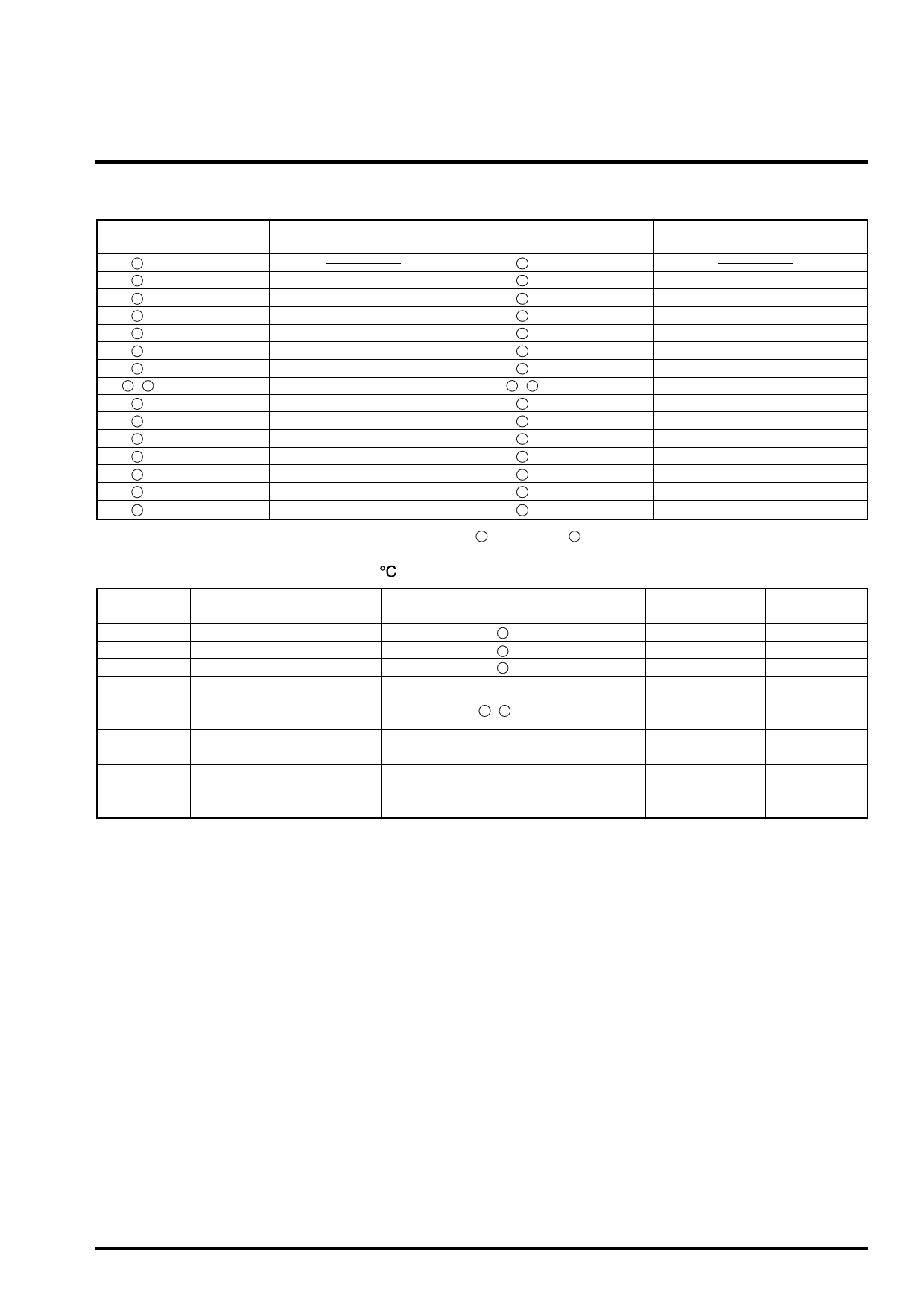
PIN DESCRIPTION
Pin No.
Symbol
Function
Pin No.
Symbol
1
2
3
4
5
6
7
8 – 14
15
16
17
18
19
20
21
N.C
S/S
RDS
FG
CI
MODE2
MODE1
GND
VM
VCC2
EC
ECR
VCC1
HB
N.C
Start / Stop
Reverse detected signal
Frequency generator output
Phase Compensation
Reverse torque mode select 2
Reverse torque mode select 1
GND
Motor supply voltage
12V supply voltage
Motor speed control
The reference voltage for EC
5V supply voltage
Bias for Hall Sensor
22
23
24
25
26
27
28
29 – 35
36
37
38
39
40
41
42
N.C
Hu+
Hu-
Hv+
Hv-
Hw+
Hw-
GND
MODE4
MODE3
RS
U
V
W
N.C
* Pull-up resistors (10kohm) are included in the circuits connected to 3 pin [RDS] and 4 pin[FG].
Function
Hu+ Sensor amp. input
Hu- Sensor amp. input
Hv+ Sensor amp. input
Hv- Sensor amp. input
Hw+ Sensor amp. input
Hw- Sensor amp. input
GND
Hall amplifier sensitivity select
Automatic stop select
Motor current sense
Motor drive output U
Motor drive output V
Motor drive output W
ABSOLUTE MAXIMUM RATING (Ta=25 )
Symbol
VM
VCC2
VCC1
Io
VH(c)
Pt
Kθ
Tj
Topr
Tstg
Parameter
Motor supply voltage
12V supply voltage
5V supply voltage
Output current
Sensor amp.
Differential input range
Power dissipation
Thermal derating
Junction temperature
Operating temperature
Storage temperature
Conditions
15 pin
16 pin
19 pin
Note 1
23 – 28 pins
Free Air
Free Air
*Note1 ; The ICs must be operated within the Pt (power dissipation) or the area of safety operation
Rating
16
16
7.0
1.5
4.5
1.2
9.6
150
-20 – +75
-40 – +125
Unit
V
V
V
A
V
W
mW/˚C
˚C
˚C
˚C
Share Link: 