APU429 데이터 시트보기 (PDF) - APLUS INTEGRATED CIRCUITS
부품명
상세내역
제조사
APU429 Datasheet PDF : 18 Pages
| |||
Functional Description
SRAM
The 256 x 4 bits index SRAM and 128 x 4 bits data SRAM are 2 separate regions.
Index ROM
The 256 x 8 bits index ROM can be used as a 4-bit mode or an 8-bit mode.
I/O ports
The IOA port can be selected by software separately as input or output, and with/without internal pull-low and
different chattering clocks in order for HALT release/ interrupt trigger to reduce the bounce of key_scan:
PH6: 512Hz PH8:128Hz PH10: 32Hz
The pull-low of the IOA will be masked off for those pins defined as output pins.
The IOA port can be used as a pseudo serial output port.
The IOB port can be selected by software separately as input or output.
The IOC port can be selected by software separately as input or output, and with/without internal pull-low and
different chattering clocks in order for HALT release/ interrupt trigger to reduce the bounce of key_scan.
The IOD port can be selected by software separately as input or output.
The IOD port can be used as a pseudo serial output port.
The initial state of all I/O ports is standard input state and IOA, C have pull-low device.
Before setting some pins from input to output, you can execute the output function to ensure their output value.
The S ports are input pins that contain pull-low. The L_L_H resistor can be selected by mask option and
different chattering clocks in the same manner as the IOA, C ports.
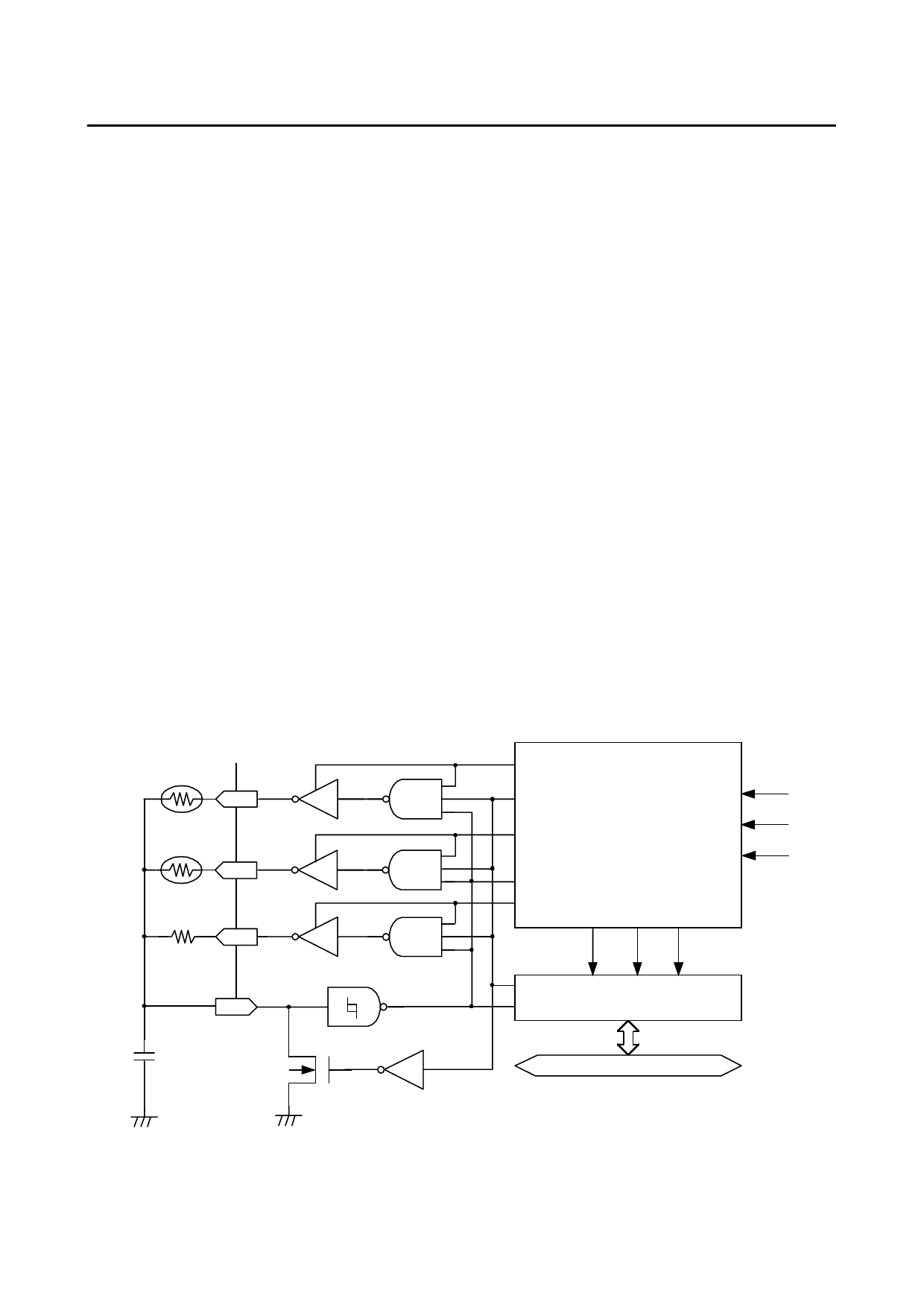
Resistor to frequency converter
We use an RC oscillation circuit and a 16-bit counter to calculate the relative resistance of temperature and
humidity sensor. The diagram is shown below:
RTP
RT
RHM
RH
Rref
RR
ELP
ENX
EHM
FIN
ERR
TMS
Timer & R/F
PH9
Controller
MRF
Freq. CL LD
ENX
Freq. CL LD
CX
FIN
16-Bit Counter
CX
4-Bit Data Bus
There are two types of methodology for measuring the input frequency: first, set FIN (i.e. CX) as the clock
input, using timer 2 as interval control or using software to directly control the interval. Second, if the FIN (CX)
frequency is too low, either because of a poor resolution for a fixed interval or a longer interval for better
Preliminary
8
Ver. 0.0
Share Link: 