ST75C176B 데이터 시트보기 (PDF) - STMicroelectronics
부품명
상세내역
제조사
ST75C176B Datasheet PDF : 17 Pages
| |||
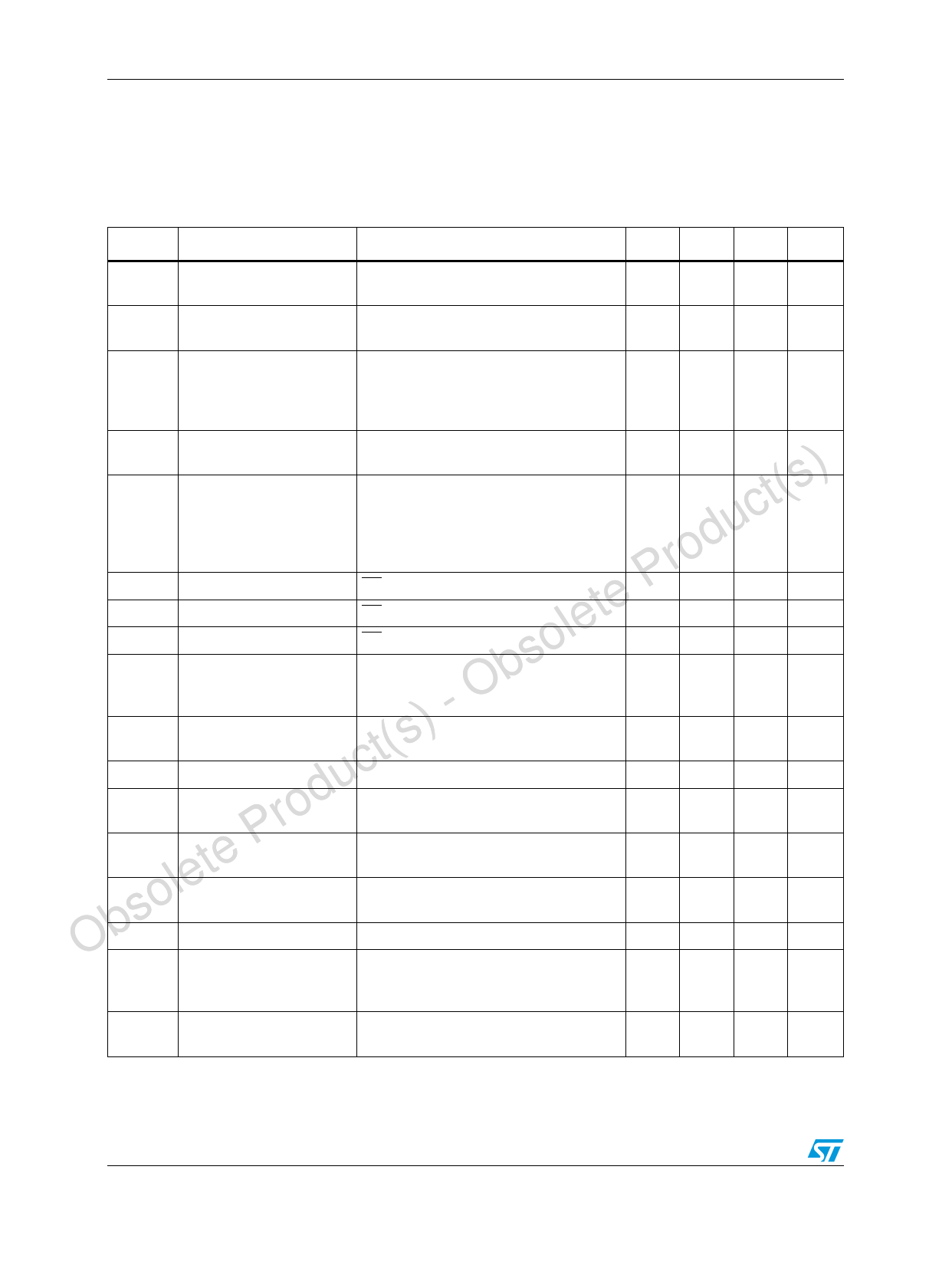
Electrical characteristics
4
Electrical characteristics
ST75C176B - ST75C176C
Table 6.
Symbol
DC electrical characteristics
(VCC = 5 V ± 5 %, TA = TMIN to TMAX, unless otherwise specified. Typical values are referred
to TA = 25 °C) (See Note 1)
Parameter
Test conditions
Min. Typ. Max. Unit
VOD1
Differential driver output
(no load)
VOD2
Differential driver output
(with load)
RL = 27Ω (RS-485), (See Figure 2.)
RL = 50Ω (RS-422), (See Figure 2.)
1.5
ΔVOD
Change in magnitude of
driver differential output
voltage for complementary
output states
RL = 27Ω or 50Ω (See Figure 2.)
5
V
5
V
5
V
0.2
V
VOC
uct(s) ΔVOC
Prod VIH
te VIL
le IIN1
bso IIN2
t(s) - O VTH
c ΔVTH
rodu VOH
P VOL
olete IOZR
ObsRIN
Driver common-mode
output voltage
RL = 27Ω or 50Ω (See Figure 2.)
Change in magnitude of
driver common-mode
output voltage for
complementary output
states
RL = 27Ω or 50Ω (See Figure 2.)
Input high voltage
RE, DE, DI
Input low voltage
RE, DE, DI
Input current
RE, DE, DI
Input current (A, B)
Receiver differential
threshold voltage
VCM = 0V or 5.25V, VDE = 0V
VIN = 12V
VIN = -7V
VCM = -7 to 12V
Receiver input hysteresis
Receiver output high
voltage
VCM = 0V
IO = -4mA, VID = 200mV
Receiver output low
voltage
IO = 4mA, VID = -200mV
3-State (high impedance)
output current at receiver
VO = 0.4 to 2.4V
Receiver input resistance VCM = -7 to 12V
3
V
0.2
V
2.0
V
0.8
V
±2
μA
1
mA
-0.8 mA
-0.2
0.2
V
70
mV
3.5
V
0.4
V
±1
μA
12
KW
ICC
No load supply current
(Note 2)
VRE = 0V or VCC
VDE = VCC
VDE = 0V
400 900 μA
300 500 μA
IOSD1
Driver short-circuit current,
VO=High
VO = -7 to 12V (Note 3)
35
250 mA
6/17
Share Link: 