AUIPS7145R 데이터 시트보기 (PDF) - International Rectifier
부품명
상세내역
제조사
AUIPS7145R Datasheet PDF : 16 Pages
| |||
AUIPS7145R
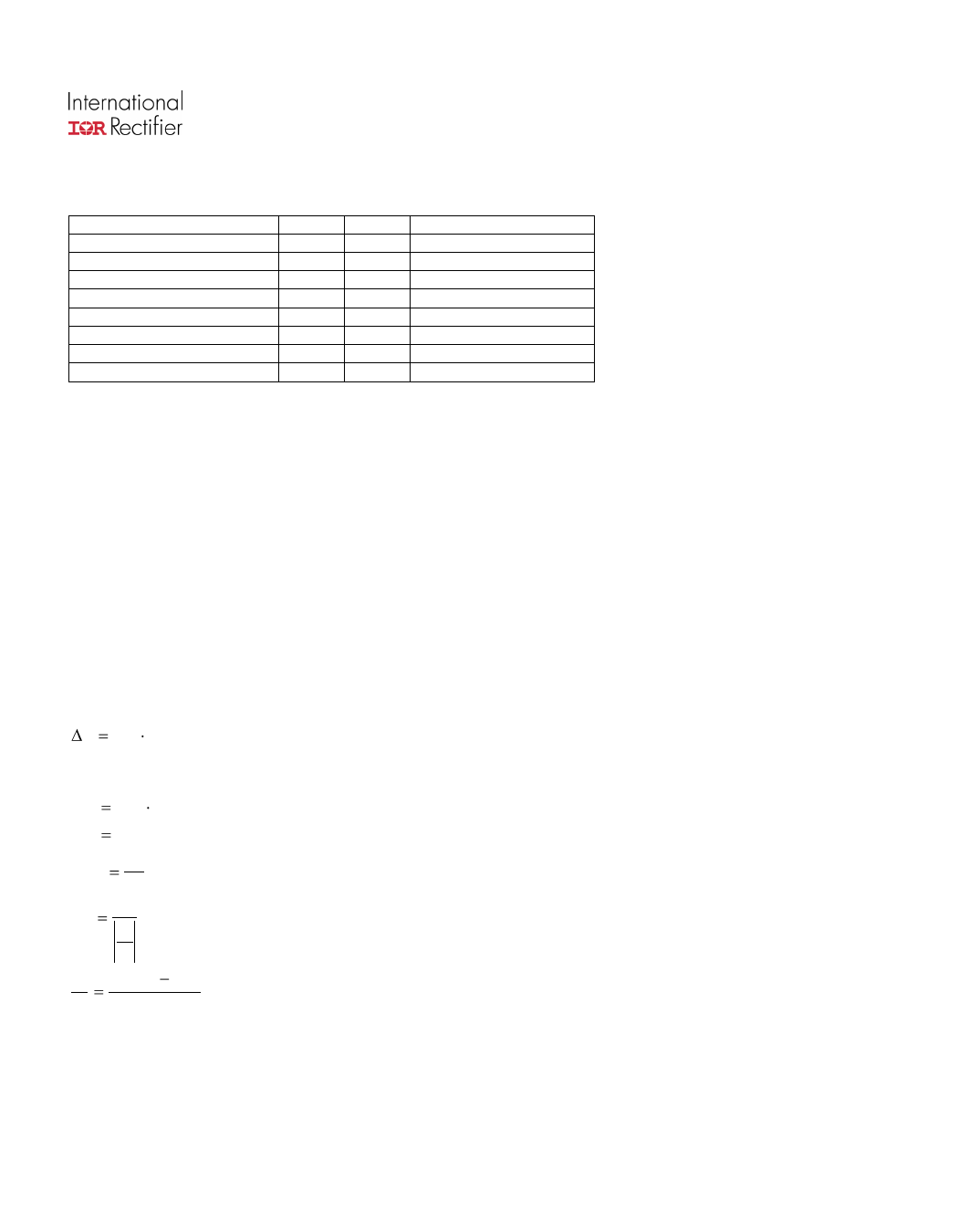
Truth Table
Op. Conditions
Normal mode
Normal mode
Open load
Open load
Short circuit to GND
Short circuit to GND
Over temperature
Over temperature
Input
H
L
H
L
H
L
H
L
Output
L
H
L
H
L
L
L
L
Ifb pin voltage
0V
I load x Rfb / Ratio
0V
0V
0V
V fault (latched)
0V
V fault (latched)
Operating voltage
Maximum Vcc voltage : this is the maximum voltage before the breakdown of the IC process.
Operating voltage : This is the Vcc range in which the functionality of the part is guaranteed. The AEC-Q100 qualification
is run at the maximum operating voltage specified in the datasheet.
Reverse battery
During the reverse battery the Mosfet is kept off and the load current is flowing into the body diode of the power Mosfet.
Power dissipation in the IPS : P = I load * Vf
There is no protection, so Tj must be lower than 150°C in the worst case condition of current and ambient temperature.
If the power dissipation is too high in Rifb, a diode in serial can be added to block the current.
The transistor used to pull-down the input should be a bipolar in order to block the reverse current. The 100ohm input
resistor can not sustain continuously 16V (see Vcc-Vin max. in the Absolute Maximum Ratings section)
Active clamp
The purpose of the active clamp is to limit the voltage across the MOSFET to a value below the body diode break down
voltage to reduce the amount of stress on the device during switching.
The temperature increase during active clamp can be estimated as follows:
Tj PCL ZTH (tCLAMP )
Where: ZTH(tCLAMP ) is the thermal impedance at tCLAMP and can be read from the thermal impedance curves given in the
data sheets.
PCL VCL ICLavg : Power dissipation during active clamp
VCL 65V : Typical VCLAMP value.
ICLavg
ICL : Average current during active clamp
2
t CL
ICL : Active clamp duration
di
dt
di VBattery VCL : Demagnetization current
dt
L
Figure 9 gives the maximum inductance versus the load current in the worst case : the part switches off after an over
temperature detection. If the load inductance exceeds the curve, a free wheeling diode is required.
www.irf.com
6
Share Link: 