STV5347 데이터 시트보기 (PDF) - STMicroelectronics
부품명
상세내역
제조사
STV5347 Datasheet PDF : 22 Pages
| |||
STV5347 - STV5347/H - STV5347/T
FUNCTIONAL DESCRIPTION (continued)
III - VPS DATA (see Table 2)
VPS data are stored in row 25 chapter 5 as shown
in Table 2 when VPS enable bit (D4 of R8 register)
is set. VPS data bits are decoded and stored in a
receivedarea with biphaseerrorbit. 8/30/2data are
stored as received (without hamming decoding) in
Row 23 chapter5 according to Table 2. 8/30 packet
and VPS data decoding is the responsibility of the
control software. The decoder simply stores trans-
mitted data.
IV - I2C Bus Register Map (see Table 3)
Registers R0 to R10 are write only whilst R11A is
a read/write and R11B is read only.
The automatic succession on a byte by byte basis
is indicated by the arrows in Table 3.
In the normal operating mode TB should be set to
logic level 0.
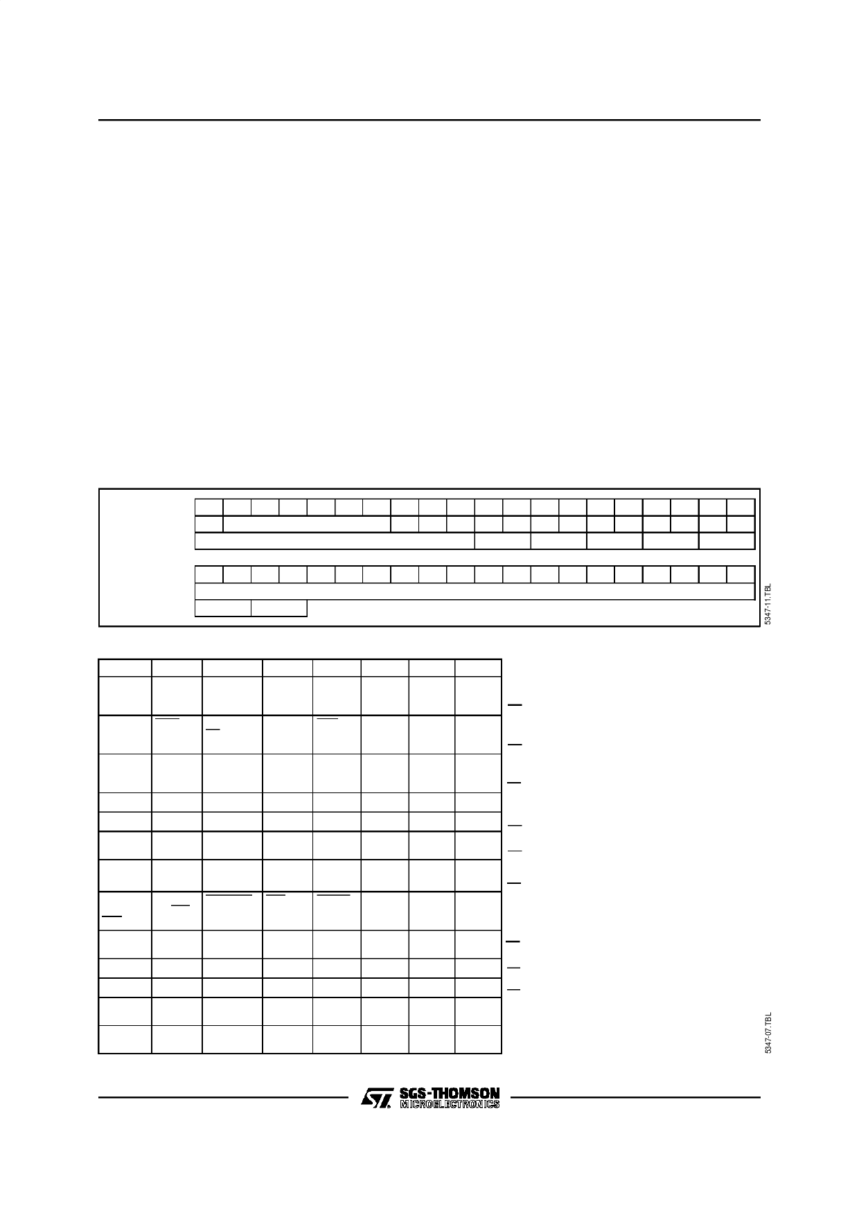
Table 2 : PDC Data Storage in Chapter 5
After power-up the contents of the registers are as
follows : all bits in registers R0 to R11Aare cleared
to zero with the exception of bits D0 and D1 in
registers R5 and R6 which are set to logical one.
After power-up all the memory bytes are preset to
hexadecimalvalue 20H (space) with the exception
of the byte corresponding to row 0 of column 7 of
chapter 0 which is set to the value corresponding
to “alpha white” hexadecimal value 07H.
In 4 pages mode, R1D4 (ghost row enable) is set
to ’0’. In this mode, the X/24, X/26, X/27, X/28
packets of the selected pages, and the 8/30 pack-
ets, are not stored.
In 2 pages mode, R1D4 (ghost row enable) is set
’1’. In this mode two displayable pages can be
stored in chapter0 and 1, and the ghost rows of the
selected pages, and the 8/30 packets, are stored
in chapter 4 and 5.
Column
0 1 2 3 4 5 6 7 8 9 10 11 12 13 14 15 16 17 18 19
8/30/2 (Row 23) D
Initial Page
b13 b14 b15 b16 b17 b18 b19 b20 b21 b22 b23 b24 b25
VPS (Row 25)
Received Page Information
B11
B12
B13
B14
B15
Column
20 21 22 23 24 25 26 27 28 29 30 31 32 33 34 35 36 37 38 39
8/30/2 (Row 23)
Status Display
VPS (Row 25) B4
B5
Table 3 : Register Specification
D7
D6
D5
X24
FREE
(1)
POSITION RUNNING
PLL
(1)
7 + P/
ACQ.
8 BIT
ON/OFF
(1)
BANK
(2)
SELECT
A2
(1)
(1)
(1)
D4
D3
DISABLE (1)
ROLLING
HEADER
GHOST
ROW
ENABLE
DEW/
FULL
FIELD
ACQ.
TB
CCT
A0
PRD4
PRD3
D2
D1
D0
EVEN
( 1)
SEL 11B
OFF
↵
T CS
T1
T0
ON
↵
START START START
COLUMN COLUMN COLUMN
SC2
SC1
SC0
↵
PRD2
PRD1
PRD0
(1)
BKGND
OUT
BKGND
OUT
(1)
BKGND
IN
BKGND
IN
(1)
COR
OUT
COR
OUT
STATUS
ROW
BTM/TOP
(1)
CURSOR
ON/OFF
(1)
CONCEAL/
REVEAL
(1)
(1)
(1)
D7
(R/W)
6 0Hz
(1)
(1)
D6
(R/W)
0
(1)
C5
D5
(R/W)
0
(1)
COR
IN
COR
IN
(1)
TEXT
OUT
TEXT
OUT
A2
T EXT
IN
T EXT
IN
TOP/
SINGLE/ BOX ON
BOTTOM DOUBLE 24
HEIGHT
VPS
CLEAR A2
ENABLE MEM.
R4
R3
R2
C4
C3
C2
D4
(R/W)
0
D3
(R/W)
0
D2
(R/W)
0
( 2)
PON
A0
PON
↵
OUT
IN
↵
PON
PON
OUT
IN
↵
BOX ON BOX ON
1-23
0
( 2)
A0
↵
R1
R0
↵
C1
C0
↵
D1
D0
(R/W) (R/W)
DATA
QUAL
VCS
QUAL
(1) Reserved register bits : must be set to 0
(2) Inactive
R0 Mode 0
R1 Mode 1
R2 Page request address
R3 Page request data
R4 Display chapter
R5 Display control (normal)
R6
Display control
(newsflash / subtitle)
R7 Display mode
R8 Active chapter
R9 Active row
R10 Active column
R11A Active data
R11B Status
9/22
Share Link: 