CDP1802AC/3 데이터 시트보기 (PDF) - Intersil
부품명
상세내역
제조사
CDP1802AC/3 Datasheet PDF : 27 Pages
| |||
CDP1802AC/3
DMA-IN or DMA-Out request is received, one machine cycle
is “stolen”. This operation occurs at the end of the execute
machine cycle in the current instruction. Register R(0) is
always used as the data pointer during the DMA operation.
The data is read from (DMA-Out) or written into (DMA-IN)
the memory location pointed to by the R(0) register. At the
end of the transfer, R(0) is incremented by one so that the
processor is ready to act upon the next DMA byte transfer
request. This feature in the 1800-series architecture saves a
substantial amount of logic when fast exchanges of blocks of
data are required, such as with magnetic discs or during
CRT-display-refresh cycles.
Data Registers
When registers in R are used to store bytes of data, four
instructions are provided which allow D to receive from or
write into either the higher-order or lower-order byte portions
of the register designated by N. By this mechanism (together
with loading by data immediate) program pointer and data
pointer designations are initialized. Also, this technique
allows scratchpad registers in R to be used to hold general
data. By employing increment or decrement instructions,
such registers may be used as loop counters.
The Q Flip-Flop
An internal flip-flop, Q, can be set or reset by instruction and
can be sensed by conditional branch instructions. The output
of Q is also available as a microprocessor output.
Interrupt Servicing
Register R(1) is always used as the program counter
whenever interrupt servicing is initiated. When an interrupt
request occurs and the interrupt is allowed by the program
(again, nothing takes place until the completion of the
current instruction), the contents of the X and P registers are
stored in the temporary register T, and X and P are set to
new values; hex digit 2 in X and hex digit 1 in P. Interrupt
Enable is automatically deactivated to inhibit further
interrupts. The user's interrupt routine is now in control; the
contents of T may be saved by means of a single instruction
(78) in the memory location pointed to by R(X). At the
conclusion of the interrupt, the user's routine may restore the
pre-interrupted value of X and P with a single instruction (70
or 71). The Interrupt Enable flip-flop can be activated to
permit further interrupts or can be disabled to prevent them.
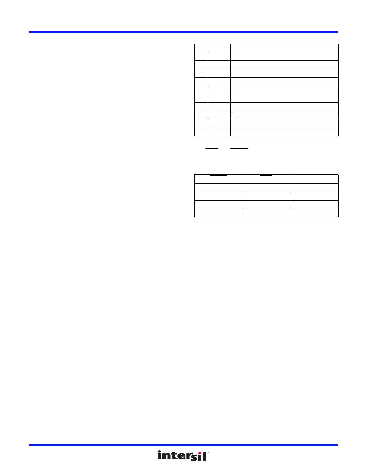
CPU Register Summary
D 8 Bits Data Register (Accumulator)
DF 1-Bit Data Flag (ALU Carry)
B 8 Bits Auxiliary Holding Register
R 16 Bits 1 of 16 Scratchpad Registers
P 4 Bits Designates which register is Program Counter
X 4 Bits Designates which register is Data Pointer
N 4 Bits Holds Low-Order Instruction Digit
I 4 Bits Holds High-Order Instruction Digit
T 8 Bits Holds old X, P after Interrupt (X is high nibble)
lE 1-Bit Interrupt Enable
Q 1-Bit Output Flip-Flop
CDP1802 Control Modes
The WAIT and CLEAR lines provide four control modes as
listed in Table 3:
TABLE 3. CONTROL MODES
CLEAR
L
L
H
H
WAIT
L
H
L
H
MODE
LOAD
RESET
PAUSE
RUN
The functions of the modes are defined as follows:
LOAD
Holds the CPU in the IDLE execution state and allows an I/O
device to load the memory without the need for a “bootstrap”
loader. It modifies the IDLE condition so that DMA-lN
operation does not force execution of the next instruction.
RESET
Registers l, N, Q are reset, lE is set and 0’s (VSS) are placed on
the data bus. TPA and TPB are suppressed while reset is held
and the CPU is placed in S1. The first machine cycle after
termination of reset is an initialization cycle which requires 9
clock pulses. During this cycle the CPU remains in S1 and
register X, P, and R(0) are reset. Interrupt and DMA servicing
are suppressed during the initialization cycle. The next cycle is
an S0, S1, or an S2 but never an S3. With the use of a 71
instruction followed by 00 at memory locations 0000 and 0001,
this feature may be used to reset IE, so as to preclude
interrupts until ready for them. Power-up reset can be realized
FN1441 Rev 3.00
October 17, 2008
Page 17 of 27
Share Link: 