GS9021A 데이터 시트보기 (PDF) - Gennum -> Semtech
부품명
상세내역
제조사
GS9021A Datasheet PDF : 26 Pages
| |||
3.6 UES Error Flag Updating
In receive mode, a UES flag is set HIGH in the outgoing
EDH packet if the corresponding UES flag was HIGH in the
incoming packet or if the corresponding V bit was LOW.
(For example, if the incoming Active Picture V bit is LOW,
the outgoing Active Picture UES bit will be HIGH). If there is
no EDH packet in the incoming data, all three UES flags
(ANC, AP, FF) are set HIGH.
CLR1
0
0
1
1
CLR0
0
1
0
1
MODE OF OPERATION
Normal
Reset Counter to Zero
Auto Reset
Hold Counter at Zero
3.7 No EDH
PIN
LOGIC OPR
HOST BIT
NO_EDH
Some input data streams may lack the EDH packet. In such
cases, the NO_EDH bit in the HOSTIF read table is
asserted HIGH. If only a few fields lack the EDH packet, the
NO_EDH bit will be asserted only for those fields.
In determining if the input data stream contains an EDH
packet, the GS9021A looks for two things. First, the
presence of an ANC packet with the header 000 3FF 3FF
1F4 and second, that the ANC header is in the right spot for
the video standard detected. The NO_EDH signal is a
logical NAND of these two cases. If either one is false, the
NO_EDH flag is set.
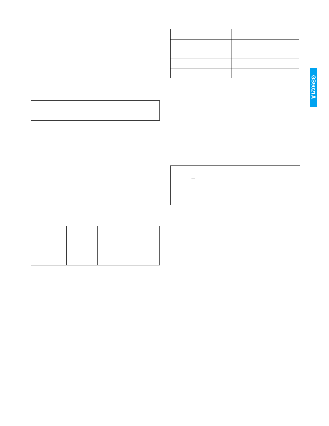
reset to zero and begins counting again. The mode of
operation will immediately return to 00 (normal mode) once
the counter resets. In "Auto Reset" mode, the counter
behaves in the normal fashion, except that it resets to zero
every time a HOSTIF read of the lowest 8 bits of the error
counter (address 17) is performed. This functionality allows
the chip to count the number of errors since the last read.
The “Hold Counter at Zero” mode instantly freezes the
counter at zero until it is moved into one of the other modes.
3.9 Flag Port
PIN
F_R/W
S[1:0]
FL[4:0]
LOGIC OPR
HOST BIT
>
OVERWRITE VALUES
3.8 Errored Field Counter
PIN
LOGIC OPR
HOST BIT
ERRORED FIELD COUNTER
CLR[1:0]
ERROR SENSITIVITY BITS
In addition to the HOSTIF tables, the EDH error flags can
also be read and written via the synchronous flag port. The
five flag port pins, FL[4:0], allow access to all 15 error flags.
The select pins S[1:0] control which flags are read/written
as outlined below. If the flag port is not going to be used, it
is best to set F_R/W HIGH, leave FL[4:0] unconnected and
set S[1:0] to any value desired but not floating.
The device has a 24 bit ERRORED FIELD COUNTER. The
counter increments by one on the occurrence of one or
more error flags in an OUTGOING EDH packet. The error
flags that can increment the counter are user-selectable
through the 16 ERROR SENSITIVITY bits in the HOSTIF
write table.
The error flag SENSITIVITY bits are active LOW, so that If a
particular sensitivity bit is set LOW, the counter is sensitive
to errors of that type in the OUTGOING EDH packet. The
EDH_CHKSM SENSITIVITY bit is active HIGH.
There are four methods of counter operation. The mode is
set through 2 bits in the HOSTIF write table, denoted CLR1
and CLR0.
In "Normal" mode the counter operates as previously
discussed, such that the counter increments on detection of
any error for which the sensitivity flags are set HIGH. If
“Reset Counter to Zero” mode is selected, the counter is
3.9.1 Write Mode
When the F_R/W pin is LOW, the flag port is in write mode
and the FL[4:0] pins are configured as inputs. After writing
to the flag port, the GS9021A inserts the written flags into
the next outgoing EDH packet. Note that external flag
overwriting via the flag port takes precedence over HOSTIF
overwriting but the flag port write only affects the next
outgoing EDH packet. Following this, if the flag port is not
written to again, flag operation is returned to normal EDH
functionality (unless it is being overwritten through the
HOSTIF).
The data present on the FL[4:0] output pins, as controlled
by the S[1:0] pins, is summarized below.
In addition to overwriting the 15 error flags, the outgoing
validity bits for the active picture (APV) and full field (FFV)
can be overwritten via the flag port.
11 of 26
19983 - 1
Share Link: 