HT82K94E_07 데이터 시트보기 (PDF) - Holtek Semiconductor
부품명
상세내역
제조사
HT82K94E_07 Datasheet PDF : 43 Pages
| |||
HT82K94E/HT82K94A
Interrupts, occurring in the interval between the rising
edges of two consecutive T2 pulses, will be serviced on
the latter of the two T2 pulses, if the corresponding inter-
rupts are enabled. In the case of simultaneous requests
the following table shows the priority that is applied.
These can be masked by resetting the EMIbit.
Interrupt Source
Priority Vector
USB interrupt
1
04H
Timer/Event Counter 0 overflow
2
08H
Timer/Event Counter 1 overflow
3
0CH
Once the interrupt request flags (TF, USBF) are set,
they will remain in the INTC register until the interrupts
are serviced or cleared by a software instruction. It is
recommended that a program does not use the ²CALL
subroutine² within the interrupt subroutine. Interrupts of-
ten occur in an unpredictable manner or need to be ser-
viced immediately in some applications. If only one stack
is left and enabling the interrupt is not well controlled, the
original control sequence will be damaged once the
²CALL² operates in the interrupt subroutine.
Oscillator Configuration
There is an oscillator circuits in the microcontroller.
O SC1
O SC2
C r y s ta l O s c illa to r
System Oscillator
This oscillator is designed for system clocks. The HALT
mode stops the system oscillator and ignores an exter-
nal signal to conserve power.
A crystal across OSC1 and OSC2 is needed to provide
the feedback and phase shift required for the oscillator.
No other external components are required. In stead of
a crystal, a resonator can also be connected between
OSC1 and OSC2 to get a frequency reference, but two
external capacitors in OSC1 and OSC2 are required.
The WDT oscillator is a free running on-chip RC oscilla-
tor, and no external components are required. Even if
the system enters the power down mode, the system
clock is stopped, but the WDT oscillator still works within
a period of approximately 31ms. The WDT oscillator can
be disabled by ROM code option to conserve power.
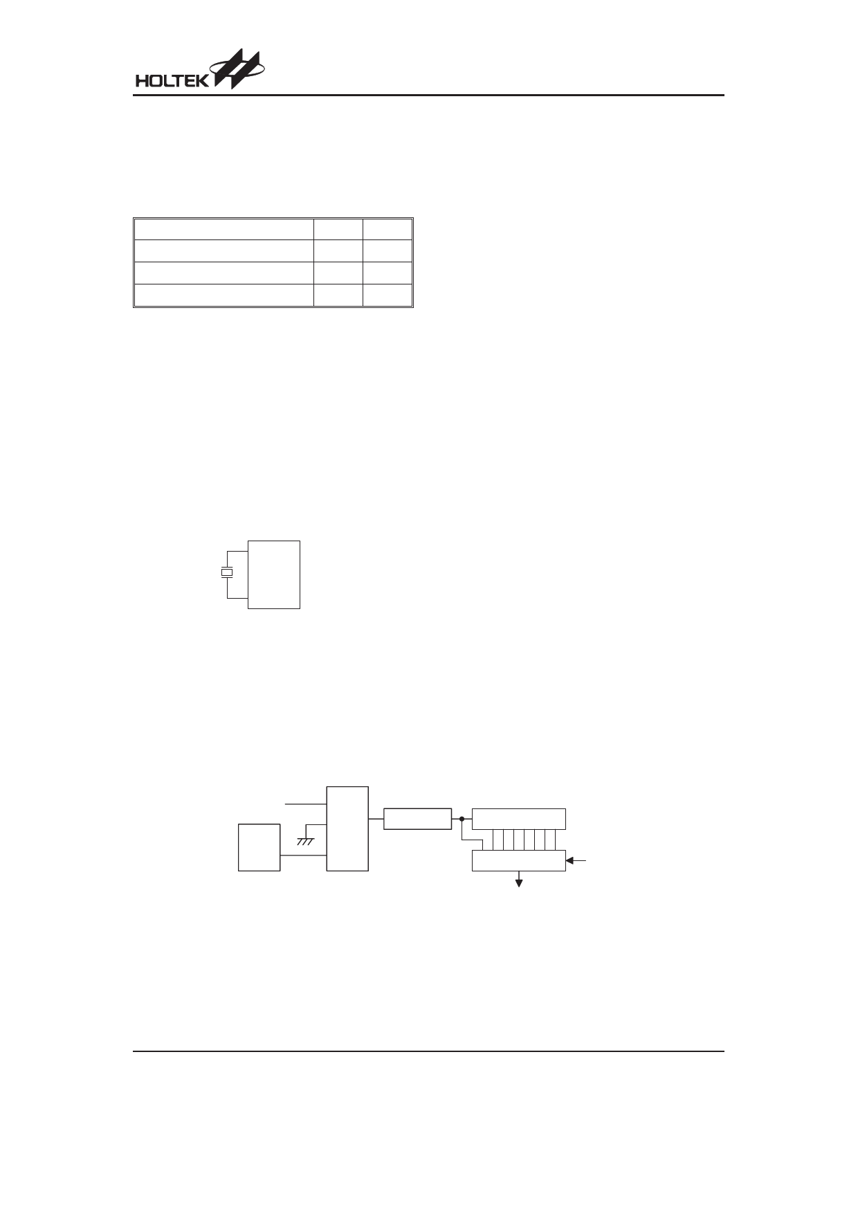
Watchdog Timer - WDT
The WDT clock source is implemented by a dedicated
RC oscillator (WDT oscillator), or instruction clock (sys-
tem clock divided by 4), determines the ROM code op-
tion. This timer is designed to prevent a software
malfunction or sequence from jumping to an unknown
location with unpredictable results. The Watchdog
Timer can be disabled by ROM code option. If the
Watchdog Timer is disabled, all the executions related
to the WDT result in no operation.
Once the internal WDT oscillator (RC oscillator, nor-
mally with a period of 31ms/5V) is selected, it is first di-
vided by 256 (8-stage) to get the nominal time-out
period of 8ms/5V. This time-out period may vary with
temperatures, VDD and process variations. By invoking
the WDT prescaler, longer time-out periods can be real-
ized. Writing data to WS2, WS1, WS0 (bits 2, 1, 0 of the
WDTS) can give different time-out periods. If WS2,
WS1, and WS0 are all equal to 1, the division ratio is up
to 1:128, and the maximum time-out period is 1s/5V. If
the WDT oscillator is disabled, the WDT clock may still
come from the instruction clock and operates in the
same manner except that in the HALT state the WDT
may stop counting and lose its protecting purpose. In
this situation the logic can only be restarted by external
logic. The high nibble and bit 3 of the WDTS are re-
served for user¢s defined flags, which can only be set to
²10000² (WDTS.7~WDTS.3).
S y s te m C lo c k /4
W DT
O SC
ROM
C ode
O p tio n
S e le c t
8 - b it C o u n te r
W D T P r e s c a le r
7 - b it C o u n te r
8 -to -1 M U X
W D T T im e - o u t
Watchdog Timer
W S 0~W S 2
Rev. 1.50
11
October 11, 2007
Share Link: 