LT5521 데이터 시트보기 (PDF) - Linear Technology
부품명
상세내역
제조사
LT5521 Datasheet PDF : 16 Pages
| |||
LT5521
APPLICATIO S I FOR ATIO
Table 6. Matching Values Using M/A-COM ETC1.6-4-2-3
Output Transformer
fOUT
2.4GHz
L1, L2
0nH
C3
C12
∆f (10dB RL)
82pF
82pF
450MHz
2.2GHz
1nH
82pF
82pF
430MHz
2.0GHz
2.7nH
82pF
82pF
400MHz
1.7GHz
4.7nH
82pF
82pF
400MHz
1.3GHz
10nH
82pF
82pF
400MHz
1.0GHz
10nH
3.9pF
1nF
500MHz
5
0
1GHz
2GHz
–5
–10
–15
–20
–25
–30
0.7
1.2
1.7
FREQUENCY (GHz)
2.2
5521 F10
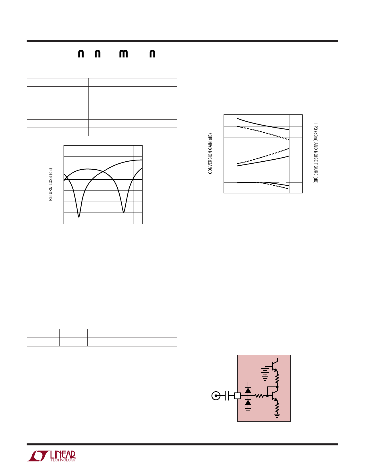
Figure 10. Output Return Loss vs Frequency
For applications with LO and output frequencies below
1GHz, the M/A-COM MABAES0054 is recommended for
the output component T2. This transformer maintains
better low frequency output symmetry. Table 7 lists com-
ponents necessary for a 750MHz output match using the
M/A-COM MABAES0054.
Table 7. Matching Values Using M/A-COM MABAES0054
Output Transformer
fOUT
L1, L2
C3
C12
∆f (10dB RL)
750MHz
33nH
82pF
1nF
500MHz
Johanson Technology supplies the 3700BL15B100S hy-
brid balun for use between 3.4GHz and 4GHz. With addi-
tional matching, this transformer can be used for
applications between 3.3GHz and 3.7GHz. Example LT5521
performance is shown in Figure 11.
10
22
8
6
TA = 25°C
4 fIF = 300MHz
2
0
–2
GC
LS
20
HS
IIP3 18
16
HS
NF
14
LS
12
LS
10
–4
3.2 3.3
HS
8
3.4 3.5 3.6 3.7 3.8
FREQUENCY (GHz)
5521 F11
Figure 11. LT5521 Performance for an Application Tuned to
3.5GHz with Low Side (LS) and High Side (HS) LO Injection
LO Interface
The LO input pin is internally matched to 50Ω. It has an
internal DC bias of 960mV. External AC coupling is re-
quired. Figure 12 shows a simplified schematic of the LO
input. Overdriving the LO input will dramatically reduce
the performance of the mixer. The LO input power should
not exceed +1dBm for normal operation. Select C1 (Figure
12) only large enough to achieve the desired LO input
return loss. This reduces external low frequency signal
amplification through the LO buffer.
For applications with LO frequency in the range of 2.1GHz
to 2.4GHz, the LT5521 achieves improved distortion and
Hybrid baluns provide a low cost alternative for differen-
tial to single-ended conversion. The critical performance
parameters of conversion gain, IIP3, noise figure and LO
suppression are largely unaffected by these transform-
ers. However, their limited bandwidth and reduced sym-
metry outside the frequency of operation degrades the
suppression of higher order LO harmonics, particularly
2xLO. Murata LBD21 series hybrid balun transformers,
for example, can be used for output frequencies as low as
840MHz and as high as 2.4GHz.
LT5521
VCC
60Ω
C1
LOIN
50Ω
8Ω
15
60Ω
5521 F12
Figure 12. Simplified LO Input Circuit
5521f
13
Share Link: 