LM25115SD 데이터 시트보기 (PDF) - National ->Texas Instruments
부품명
상세내역
제조사
LM25115SD Datasheet PDF : 17 Pages
| |||
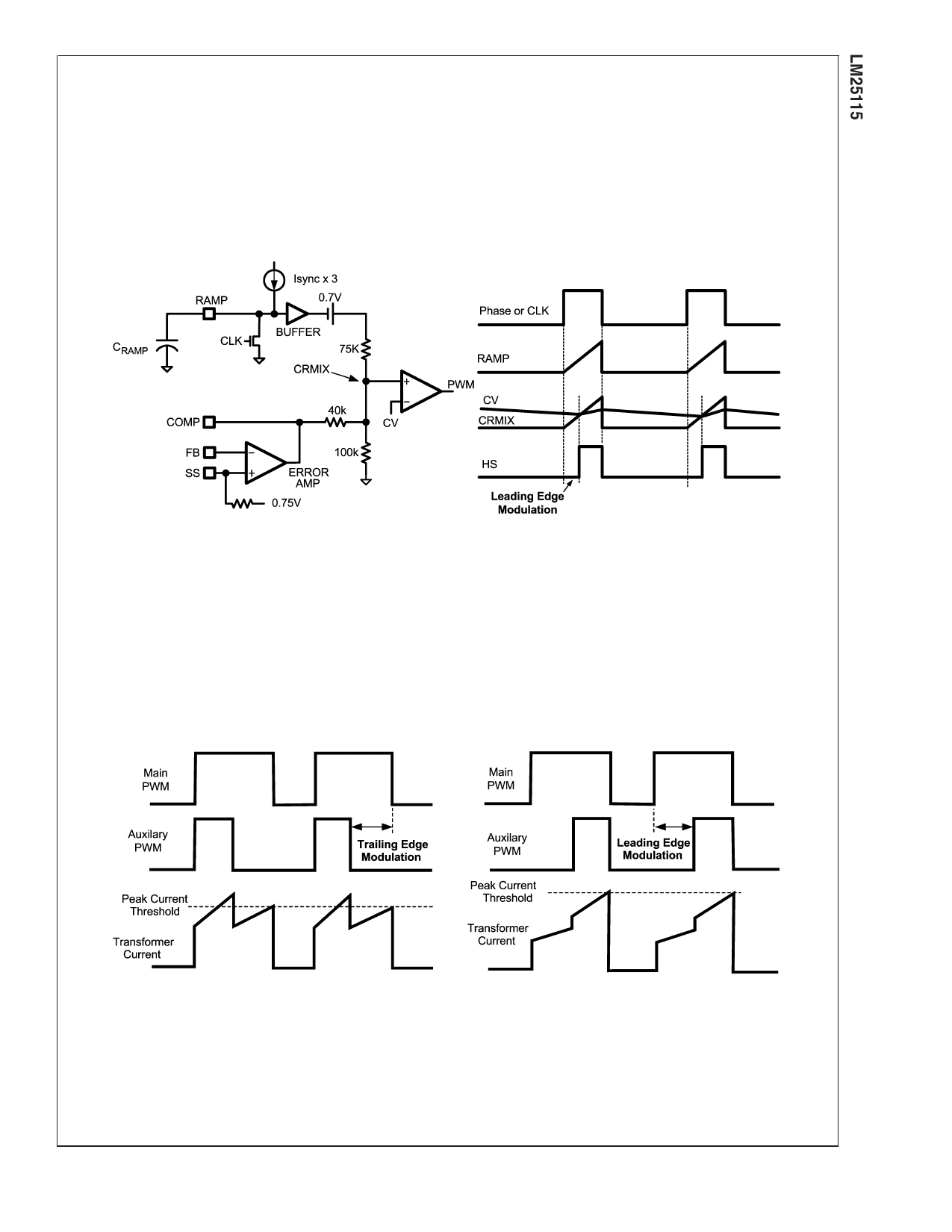
Leading Edge Pulse Width
Modulation
Unlike conventional voltage mode controllers, the LM25115
implements leading edge pulse width modulation. A current
source equal to 3 times the ISYNC current is used to charge
the capacitor connected to the RAMP pin as shown in Figure
4. The ramp signal and the output of the error amplifier
(COMP) are combined through a resistor network to produce
a voltage ramp with variable dc offset (CRMIX in Figure 4).
The high side MOSFET which drives the HS pin is held in the
off state at the beginning of the phase signal. When the
voltage of CRMIX exceeds the internal threshold voltage CV,
the PWM comparator turns on the high side MOSFET. The
HS pin rises and the MOSFET delivers current from the main
converter phase signal to the output of the auxiliary regula-
tor. The PWM cycle ends when the phase signal falls and
power is no longer supplied to the drain of the high side
MOSFET.
FIGURE 4. Synchronization and Leading Edge Modulation
20172614
Leading edge modulation of the auxiliary PWM controller is
required if the main converter is implemented with peak
current mode control. If trailing edge modulation were used,
the additional load on the transformer secondary from the
auxiliary channel would be drawn only during the first portion
of the phase signal pulse. Referring to Figure 5, the turn off
the high side MOSFET of the auxiliary regulator would cre-
ate a non-monotonic negative step in the transformer cur-
rent. This negative current step would produce instability in a
peak current mode controller. With leading edge modulation,
the additional load presented by the auxiliary regulator on
the transformer secondary will be present during the latter
portion of the phase signal. This positive step in the phase
signal current can be accommodated by a peak current
mode controller without instability.
FIGURE 5. Leading versus Trailing Edge Modulation
20172620
11
www.national.com
Share Link: 