OR4E10 데이터 시트보기 (PDF) - Agere -> LSI Corporation
부품명
상세내역
제조사
OR4E10 Datasheet PDF : 124 Pages
| |||
ORCA Series 4 FPGAs
Preliminary Data Sheet
December 2000
Programmable Logic Cells (continued)
Logic Mode
The PFU diagram of Figure 3 represents the logic
mode of operation. In logic mode, the eight LUTs are
used individually or in flexible groups to implement user
logic functions. The latches/FFs may be used in con-
junction with the LUTs or separately with the direct
PFU data inputs. There are three basic submodes of
LUT operation in PFU logic mode: F4 mode, F5 mode,
and the F6 mode. Combinations of the submodes are
possible in each PFU.
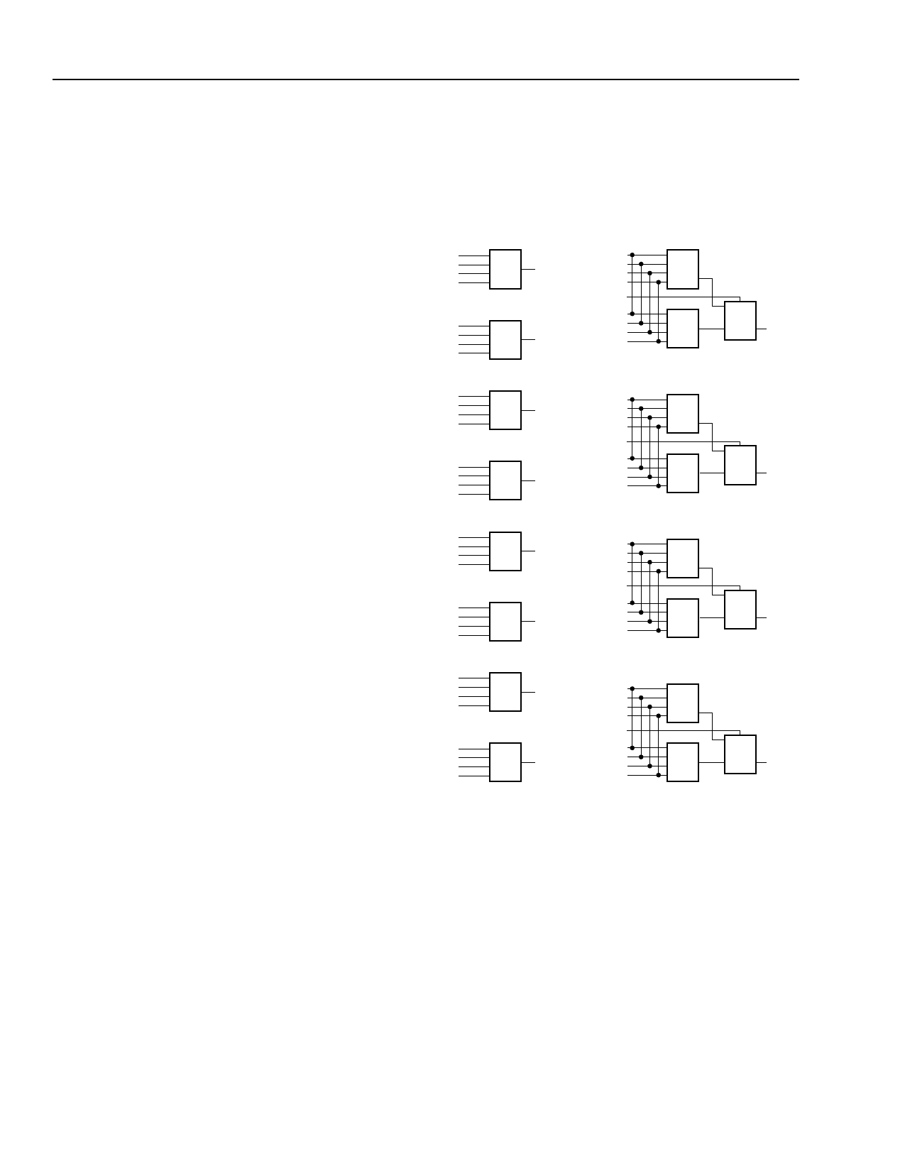
F4 mode, shown simplified in Figure 4, illustrates the
uses of the basic 4-input LUTs in the PFU. The output
of an F4 LUT can be passed out of the PFU, captured
at the LUTs associated latch/FF, or multiplexed with the
adjacent F4 LUT output using one of the F5[A:D] inputs
to the PFU (not shown). Only adjacent LUT pairs (K0
and K1, K2 and K3, K4 and K5, K6 and K7) can be multi-
plexed, and the output always goes to the even-num-
bered output of the pair.
The F5 submode of the LUT operation, shown simpli-
fied in Figure 4, indicates the use of 5-input LUTs to
implement logic. 5-input LUTs are created from two
4-input LUTs and a multiplexer. The F5 LUT is the
same as the multiplexing of two F4 LUTs described
previously with the constraint that the inputs to both F4
LUTs be the same. The F5[A:D] input is then used as
the fifth LUT input. The equations for the two F4 LUTs
will differ by the assumed value for the F5[A:D] input,
one F4 LUT assuming that the F5[A:D] input is zero,
and the other assuming it is a one. The selection of the
appropriate F4 LUT output in the F5 MUX by the
F5[A:D] signal creates a 5-input LUT.
Two 6-input LUTs are created by shorting together the
inputs of four 4-input LUTs (K0:3 and K4:7) which are
multiplexed together. The F5 inputs of the adjacent F4
LUTs derive the fifth and sixth inputs of the F6 mode as
shown in Figure 5. The F6 outputs, LUT603 and
LUT647, are dedicated to the F6 mode or can be used
as the outputs of MUX8x1. MUX8x1 modes as shown
in Figure 7 are created by programming adjacent
4-input LUTs to 2x1 MUXs and multiplexing down to
create MUX8x1. Other functions can be implemented
from the configuration shown in Figure 5 where the four
LUT4s drive the 4x1 MUX in each half of the PFU if the
LUT4 inputs are not tied to the same inputs. Both F6
mode and MUX8x1 are available in the upper and
lower PFU nibbles.
Any combination of F4 and F5 LUTs is allowed per
PFU using the eight 16-bit LUTs. Examples are eight
F4 LUTs, four F5 LUTs, a combination of four F4 plus
two F5 LUTs, a combination of two F4, one F5, plus
one F6, or a combination of one F5, one MUX21 of two
LUT4s, and one MUX41 of four LUT4s.
K7
F7
K6
F6
K7_0
K7_1
K7_2
K7_3
F5D
K6_0
K6_1
K6_2
K6_3
LUT4
LUT4
2x1
MUX F6
K5
F5
K4
F4
K5_0
K5_1
K5_2
K5_3
F5C
K4_0
K4_1
K4_2
K4_3
LUT4
LUT4
2x1
MUX F4
K3
F3
K2
F2
K3_0
K3_1
K3_2
K3_3
F5B
K2_0
K2_1
K2_2
K2_3
LUT4
LUT4
2x1
MUX F2
K1
F1
K0
F0
K1_0
K1_1
K1_2
K1_3
F5A
K0_0
K0_1
K0_2
K0_3
LUT4
LUT4
2x1
MUX F0
5-9733(F)
Figure 4. Simplified F4 and F5 Logic Modes
12
Lucent Technologies Inc.
Share Link: 