OR4E10 데이터 시트보기 (PDF) - Agere -> LSI Corporation
부품명
상세내역
제조사
OR4E10 Datasheet PDF : 124 Pages
| |||
Preliminary Data Sheet
December 2000
ORCA Series 4 FPGAs
Programmable Logic Cells (continued)
The ripple mode can be used in one of four submodes.
The first of these is adder-subtractor submode. In
this submode, each LUT generates three separate out-
puts. One of the three outputs selects whether the
carry-in is to be propagated to the carry-out of the cur-
rent LUT or if the carry-out needs to be generated. If
the carry-out needs to be generated, this is provided by
the second LUT output. The result of this selection is
placed on the carry-out signal, which is connected to
the next LUT carry-in or the COUT/FCOUT signal, if it
is the last LUT (K7/K3). Both of these outputs can be
any equation created from KZ[1] and KZ[0], but in this
case, they have been set to the propagate and gener-
ate functions.
The third LUT output creates the result bit for each LUT
output connected to F[7:0]/F[3:0]. If an adder/subtrac-
tor is needed, the control signal to select addition or
subtraction is input on F5A/F5C inputs. These inputs
generate the controller input AS. When AS = 0, this
function performs the adder, A + B. When AS = 1, the
function performs the subtractor, A – B. The result bit is
created in one-half of the LUT from a single bit from
each input bus KZ[1:0], along with the ripple input bit.
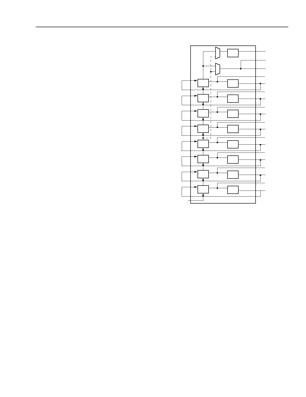
The second submode is the counter submode (see
Figure 10). The present count, which may be initialized
via the PFU DIN inputs to the latches/FFs, is supplied
to input KZ[0], and then output F[7:0]/F[3:0] will either
be incremented by one for an up counter or decre-
mented by one for a down counter. If an up/down
counter is needed, the control signal to select the direc-
tion (up or down) is input on F5A and F5C. When
F5[A:C], respectively per nibble, is a logic 1, this indi-
cates a down counter and a logic 0 indicates an up
counter.
K7[0]
K6[0]
K5[0]
K4[0]
K3[0]
K2[0]
K1[0]
K0[0]
C
DQ
C
K7
DQ
K6
DQ
K5
DQ
K4
DQ
K3
DQ
K2
DQ
K1
DQ
K0
DQ
REGCOUT
FCOUT
COUT
F7
Q7
F6
Q6
F5
Q5
F4
Q4
F3
Q3
F2
Q2
F1
Q1
F0
Q0
CIN/FCIN
Figure 10. Counter Submode
5-5756(F)
Lucent Technologies Inc.
17
Share Link: 