MB91354A 데이터 시트보기 (PDF) - Fujitsu
부품명
상세내역
제조사
MB91354A Datasheet PDF : 111 Pages
| |||
MB91350A Series
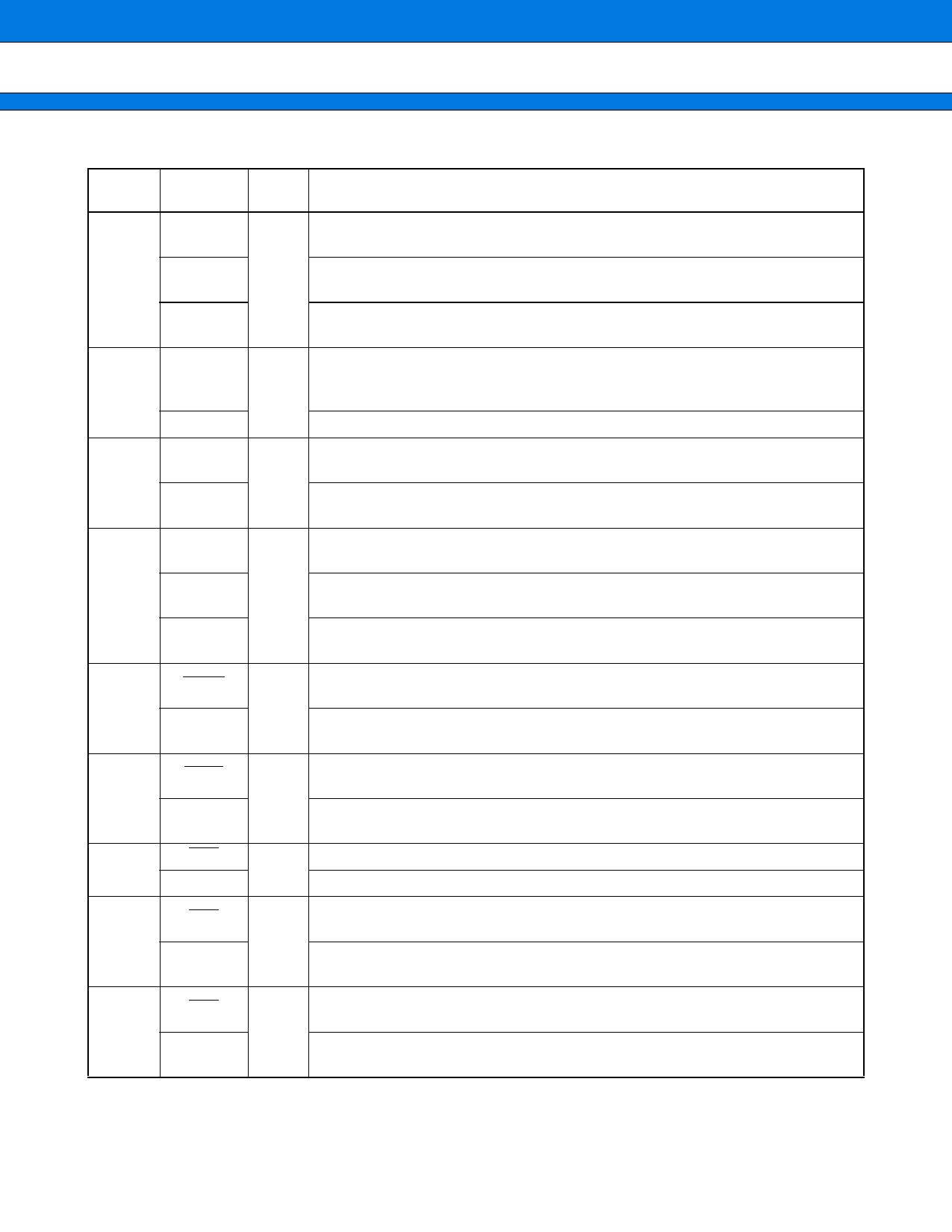
Pin no.
152
153
154
155
156
157
158
159
160
Pin name
Circuit
type
Description
DEOP0
Completion output for DMA external transfer. This function is enabled when the
external transfer end output for DMA is enabled.
DSTP0
C
Stop input for DMA external transfer. This function is enabled when the external
transfer stop input for DMA is enabled.
PB2
General purpose input/output port. This function is enabled when the external
transfer end output and external transfer stop input for DMA are disabled.
DREQ1
External input for DMA transfer requests. Since this input is used as required
when selected as a DMA start source, the port output must remain off unless in-
C tentionally turned on.
PB3
General purpose input/output port.
DACK1
PB4
External acknowledge output for DMA transfer requests. This function is enabled
when the transfer request acceptance output for DMA is enabled.
C
General purpose input/output port. This function is enabled when the external
transfer request acceptance output for DMA is disabled.
DEOP1
Completion output for DMA external transfer. This function is enabled when the
external transfer end output for DMA is enabled.
DSTP1
C
Stop input for DMA external transfer. This function is enabled when the external
transfer stop input for DMA is enabled.
PB5
General purpose input/output port. This function is enabled when the external
transfer end output and external transfer stop input for DMA are disabled.
IOWR
PB6
Write strobe output for DMA fly-by transfer. This function is enabled when the
DMA fly-by transfer write strobe output is enabled.
C
General purpose input/output port. This function is enabled when the DMA fly-by
transfer write strobe output is disabled.
IORD
PB7
Read storobe output for DMA fly-by transfer. This function is enabled when the
DMA fly-by transfer read strobe output is enabled.
C
General purpose input/output port. This function is enabled when the DMA fly-by
transfer read strobe output is disabled.
CS0
Chip select 0 output. Enable at external bus mode
C
PA0
General purpose input/output port. This is enabled at single chip mode.
CS1
Chip select 1 output. This function is enabled when the chip select 1 output is en-
abled.
C
PA1
General purpose input/output port. This function is enabled when the chip select
1 output is disabled.
CS2
Chip select 2 output. This function is enabled when the chip select 2 output is en-
abled.
C
PA2
General purpose input/output port. This function is enabled when the chip select
2 output is disabled.
(Continued)
11
Share Link: 