IS25F011A 데이터 시트보기 (PDF) - Integrated Silicon Solution
부품명
상세내역
제조사
IS25F011A
Integrated Silicon Solution

IS25F011A Datasheet PDF : 23 Pages
| |||
IS25F011A
IS25F021A
IS25F041A
ISSI ®
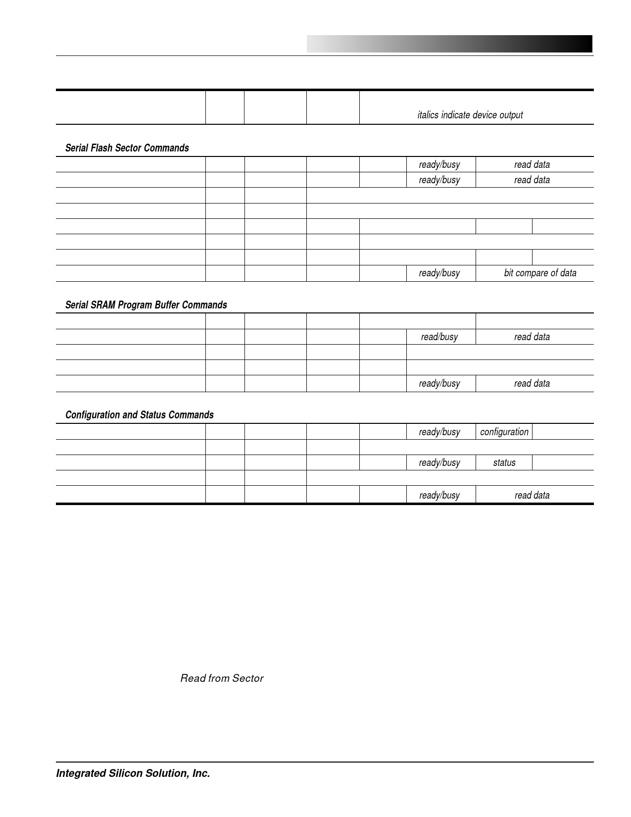
Table 3. Command Set for the IS25F011A, IS25F021A, and IS25F041A Serial Flash Memory
n - bytes
Command Name
Byte 0 Byte 1-2 Byte 3-4
(italics indicate device output)
1
Serial Flash Sector Commands
Read from Sector
Read from Sector Low Frequency
Write Enable*
Write Disable*
Write to Sector
Transfer SRAM to Sector
Transfer Sector to SRAM
Compare Sector with SRAM
52H sector addr. byte add. 0000H ready/busy
51H sector addr. byte add. 0000H ready/busy
06H
00H
04H
00H
F3H sector addr. byte add.
write data
F3H sector addr. 0000H
54H sector addr. byte add.
clock 00H per byte
86H sector addr. byte add. 0000H ready/busy
read data
read data
2
00H
3
00H
bit compare of data
4
Serial SRAM Program Buffer Commands
Write to SRAM**
Read from SRAM*
82H
0000H
byte add.
write data
81H
0000H
byte add. 0000H read/busy
00H
read data
5
Transfer SRAM to Prog. Buffer
92H
0000H
0000H 0000H
Transfer Prog. Buffer to SRAM
55H
0000H
0000H 0000H
Read from Program Buffer
91H
0000H
byte add. 0000H ready/busy
read data
6
Configuration and Status Commands
Read Configuration Register*
8BH
0000H
0000H 0000H ready/busy configuration
7
Write Configuration Register
8AH configuration 0000H
Read Status Register*
83H
0000H
0000H 0000H ready/busy
status
Clear Compare Sector*
Read Device Information Sector
89H
0000H
15H
0000H
byte add. 0000H ready/busy
read data
8
Notes:
1. * Command may be used when device is busy
2. ** Command may not be used when device is busy and TR bit=0
9
SERIAL FLASH SECTOR COMMANDS
Read From Sector
Reading from a sector is accomplished by first bringing
CS low then shifting in the Read from Sector command
(52H) followed by its 16-bit “sector-address” field. Al-
though the sector-address field is 16-bits, only bits
S[8:0] for the IS25F011A (0-1FFH), S[9:0] for the
IS25F021A (0-3FFH), S[10:0] for the IS25F041A
(0-7FFH) are used. The uppermost sector address bits
10
11
are not used but must be clocked using 0 for data. Next
a 16-bit “byte-address” field is clocked into the device
12 to designate the starting location within the 264-byte
sector. Only B[8:0] of the byte-address field are used;
the uppermost bits are not used but must be clocked in
(use 0 for data). Only byte-addresses of 0 to 107H
(264 bytes) are valid.
Integrated Silicon Solution, Inc.
11
PRELIMINARY SF001-1A
06/24/98
Share Link: